|
|
ENCYCLOPEDIA OF RADIO ELECTRONICS AND ELECTRICAL ENGINEERING Programmable frequency synthesizer. Encyclopedia of radio electronics and electrical engineering
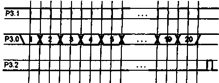
Encyclopedia of radio electronics and electrical engineering / Application of microcircuits Control of the frequency synthesizer with any change in parameters, the code is generated and transmitted to the frequency synthesizer in accordance with the diagram in fig. 5.
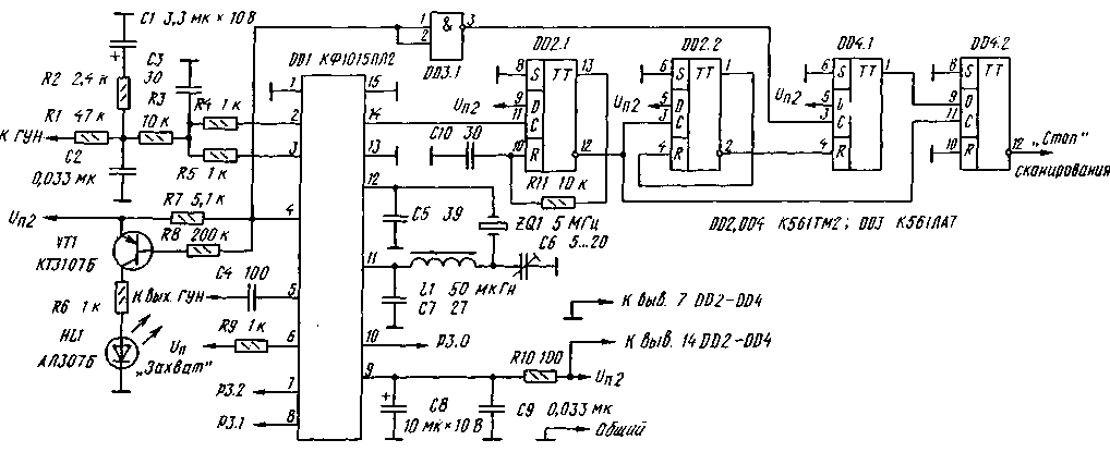
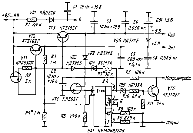
There is a transmission mode key ("transmission mode"), which determines the algorithm for calculating the code for the synthesizer (see Table 3); when the key is pressed, mode 2 is active. Turning on the DD1 synthesizer chip is shown in fig. 6. From pins 2, 3 DD1, the control signal through the filters R4R5C3 and R3C2 is fed to the VCO varicaps. Its RF output voltage is applied to pin 5 of DD1. When the frequency is "captured", the HL1 indicator is extinguished. A tuning capacitor in the quartz resonator circuit is necessary to set the exact value of the synthesized frequency. Microcircuits DD2-DD4 generate a scan inhibit signal in the presence of mismatch pulses at pin 4 of DD1. The presence of a resistor in the power circuit DD1 (pin 9) is required. The device is powered by two voltage stabilizers +5 V; their scheme is shown in fig. 7. Transistor VT1 (with parameters iots = 0,55 V, Ic = 150 μA) limits the current of transistors VT2 and VT3 at 50 mA. Transistor VT4 (at Uots = 2,5 V and Ic = 100 μA) is a +2,5 V reference voltage stabilizer. If the input voltage of the stabilizers drops to +6,5 V, the DA1 microcircuit exits the stabilization mode. When the voltage at pin 6 OA1 is +4 V, the transistor VT5 generates a low-level "micro-consumption" signal. The capacitor C5 of the stabilizer (with a low leakage current) supports Up1 when the input voltage is turned off before switching to the micro-consumption mode from the battery or galvanic cell QB1. The lower threshold Up1 in this mode should be +0,5 V. The programmable frequency synthesizer operates in two main modes: - maintaining the set (current) frequency (the "line number" indicator is extinguished); - overview of the memory of fixed frequency values (the "line number" indicator shows the number of the working "line" of the memory). The transition to the current frequency mode is made by the "Current" key, and to the frequency memory access mode - by the "Memory*" key. Pressing the "Memory" key again switches to the zero "line" of the memory. or below the current one) occurs in a ring between the initial and final scanning frequencies (L.S. and K.S.) with a step specified by the Grid parameter. In the memory sweep mode, the locked frequency values are scanned in a ring between the start and end "lines" of memory (H.speed and F.speed). Scanning is controlled by the "Scan" key. When the key is pressed once for less than 0,5 s, the transition to one step occurs, and after a long press (more than 0,5 s), the controller switches to continuous scanning mode. In this mode, if there is a signal from the receiver's squelch, scanning will temporarily stop for 5 s; at the signal "stop scanning" the scanning stops. It is resumed by pressing the "Scan" button again. After turning on the power, the device is set to the current frequency mode with the following parameter values: - Grid - 000001; - CD - 10; - IF -000000; - Frustration. - 000000; - Current frequency - 000992; - N.sk. and K.sk. for scanning by frequency - 000000; - Frequency of "line 0" of memory - 000992 (other "lines" of memory - 000000); - N.sk. and K.sk. for scanning along the "lines" of memory - 00. These initial parameter values can be changed to suit the application of the synthesizer. Recommended order of work: We select the values of the Mesh and CD parameters from the following considerations: 1. The grid sets the step of transition from frequency to frequency and its value must be an integer. This parameter is set in thousands or hundreds of Hz (three or two least significant digits of the absolute frequency value are not displayed), while the remaining frequency parameters are entered in the units of measurement corresponding to this condition. 2. The current frequency value divided by the Grid value must be between 992-131071. 3. The frequency of the crystal oscillator of the synthesizer is equal to the CD value multiplied by the Grid step. 4. CD can take values: 10, 20, 40, 100, 200, 400, 800 and 1000. Changing or entering parameters is done using the digital dialing keys, starting from the highest digit. An erroneously typed number is canceled with the "Yawn" key. The "Reset" button achieves a return to the previously set initial parameters. An error indication ("E" sign) indicates the impossibility of correct calculation of the code according to the entered parameters. Parameters Grid, CD, IF and Descatter. are controlled and changed regardless of the operating mode when the corresponding key is pressed. The desired value of the CD is selected with the "+/-" key. IF and Detune parameters have a sign, which is changed by the "+/-" key, and the *-* sign indication corresponds to the pressed key. To control and change the current frequency, use direct dialing in the current frequency mode. Entering the start and end frequencies for scanning by frequency occurs with the pressed keys •Sk." and Hek.1', respectively. Monitoring and changing the frequency in the memory is carried out in the appropriate mode, while the number of the controlled "line" of the memory is reflected on the indicator. The input frequency is written to the next "line". For example, to write to "line 0", the indicator should have the number "09". Clearing the "line O", i.e. entry 000000 is not allowed. The transition to the next or previous "line" is performed using the "Scan." according to the start and end "strings" for the memory scan, while blank (empty) "strings" are ignored. Control and change of the initial and final "lines" of the memory occur when the "H.sk." key is pressed. and "K.sk." accordingly, the number of the "line" and the frequency recorded in it are displayed. In this way, all "lines" of memory can be viewed. Changing the scanning direction is done with the "+/-" key (only the "-*" sign is displayed). The detuning is turned on and off using the "Bl. register." key, while the displayed sign "M" means that there is no detuning. In this case, the controller calculates the code for the synthesizer without taking into account the "Dist" parameter. To switch from the "Receive" mode to the "Transmit" mode, press the "Send/Transfer" key. In this case, the code is written to the synthesizer, and after 21 ms a low-level signal is generated to turn on the transmitter (pin РЗ.5), the load current is less than 10 mA. In the continuous scan mode, the indication of the frequency and number of the "line" of the memory is turned off. When the supply voltage drops below +5 V, the controller enters the micro-consumption mode. When the power is turned on again, the RST signal returns the controller to the operating mode that preceded the transition to the micro-current consumption mode. The design of a programmable synthesizer is largely determined by the scope of its application: stationary or portable equipment, operating frequency range, use of external memory. In any case, it should be borne in mind that the installation of the device must be compact and meet the requirements for high-speed digital devices. High-frequency nodes are performed in accordance with a minimum of parasitic connections and installation capacitances. In stationary equipment, large microcircuits are best installed in sockets. The device can use the keyboard and indicators from eight-digit microcalculators. The design used MLT-0,125 resistors and precise C2-29V resistors. Polar capacitors - type K53-1 or similar, non-polar capacitors - ceramic, small-sized, for example K10-17. The scope of the proposed synthesizer is quite wide, therefore, a specific VCO circuit is not given: the options for its construction depend on the operating frequency range, on the elements that the radio amateur has. Almost any range of VCOs can be built according to the scheme of one of the master oscillators of a broadband microwave oscillator, described in "Radio", No. 8 and 9 for 1992. The lowest operating frequency of the synthesizer may be below 50 MHz, it depends on the specific instance of the KF1015PL2 microcircuit. Changes to the controller program are possible, taking into account its specific application. Author: V. Semenov, V. Shlektarev, Pushchino, Moscow Region; Publication: N. Bolshakov, rf.atnn.ru
Machine for thinning flowers in gardens
02.05.2024 Advanced Infrared Microscope
02.05.2024 Air trap for insects
01.05.2024
▪ Raising a dog is like raising a child. ▪ New series of ultra-bright white LEDs HLMP ▪ RF Integrated Circuits ADL537x
▪ section of the site The most important scientific discoveries. Article selection ▪ article When I did not drink tears from the cup of being. Popular expression ▪ article What is a stalactite? Detailed answer ▪ article Common apricot. Legends, cultivation, methods of application ▪ article Automatic power switching. Encyclopedia of radio electronics and electrical engineering
Home page | Library | Articles | Website map | Site Reviews www.diagram.com.ua |


 Arabic
 Bengali
 Chinese
 English
 French
 German
 Hebrew
 Hindi
Hindi Italian
 Japanese
 Korean
 Malay
Malay Polish
 Portuguese
 Spanish
 Turkish
 Ukrainian
 Vietnamese


 Leave your comment on this article: