
|
|
ENCYCLOPEDIA OF RADIO ELECTRONICS AND ELECTRICAL ENGINEERING Some schemes on tunnel diodes. Encyclopedia of radio electronics and electrical engineering
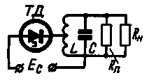
Encyclopedia of radio electronics and electrical engineering / Miscellaneous electronic devices The simplest way is to build self-oscillator circuits using tunnel diodes. Since the tunnel diode is a two-terminal device with a negative resistance, stable in voltage, when a parallel oscillatory circuit is connected to it, it can generate. In this case, the negative resistance of the diode will compensate for the losses, and undamped oscillations can arise and be maintained in the circuit. Conventional low-frequency tunnel diodes work well at frequencies equal to units of megahertz. Higher frequency diodes, in which the junction capacitance and lead inductance are reduced, generate at frequencies of thousands of megahertz. However, due to the small values of the section of the current-voltage characteristic of a diode with negative resistance, the power given by it at any frequency is fractions of a mW. So that the shape of the generated oscillations is not distorted, as a rule, a partial connection of the diode to the generator circuit is used. In this case, the loss resistance given to the diode terminals must be equal to its negative resistance. In real circuits, the reduced loss resistance is chosen to be greater than the negative one. resistance of the tunnel diode in order to guarantee reliable excitation of the generator with changes in temperature, supply voltage and frequency. Given that the parallel loss resistance in real oscillatory circuits significantly exceeds the resistance of a tunnel diode, the tap must be made from a small part of the turns of the circuit (Fig. 1). Part of the vibrational power will be released on the internal resistance of the bias source, so it should be as small as possible.
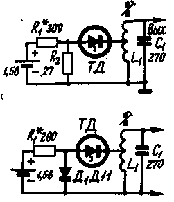
Typically, tunnel diodes are powered by a voltage divider, which wastes power. Indeed, for germanium diodes, the bias voltage in the generation mode is 0,1-0,15 V, and the minimum voltage of the vast majority of chemical current sources is 1,2-2 V, which is why it is necessary to use voltage dividers in the power circuit. In this case, approximately 80-90% of the total power consumption is dissipated in the divider. For reasons of economy, it is advisable to use sources with the lowest possible voltage to power tunnel diodes. The output impedance of the voltage divider is chosen in the range of 5-10 ohms, and only in devices where the greatest efficiency is required is it increased to 20-30 ohms. The negative resistance of the tunnel diode should exceed the resistance of the divider by 5-10 times. It is not advisable to shunt such small resistances with capacitors to reduce high-frequency energy losses, since in some cases this can lead to unstable operation of the generator, especially if its mode was selected according to the maximum output power. The negative resistance of the tunnel diode is highly dependent on the position of the operating point, so that if the supply voltage changes by 10%, the normal operation of the generator can be completely disrupted. Therefore, when powering diodes from chemical current sources - batteries, accumulators, it is very difficult to ensure their stable operation. It is most advisable to power them from mercury oxide elements, the voltage of which changes slightly during operation, and in some cases it is necessary to use a pre-stabilized voltage or use non-linear resistances in the divider - in the upper arm, stabilizing the current, and in the lower arm - voltage. So, if in the oscillator circuit (Fig. 2, a) instead of the resistance R2, a germanium diode D11 is used in direct connection, as shown in fig. 2, b, the stability of the generator will improve and when the supply voltage changes from 1,5 to 1 V, no adjustments are required.
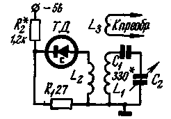
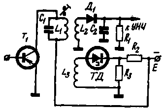
In the above diagrams of self-oscillators at a frequency of 465 kHz, the L1 coil is wound on a 4-section polystyrene frame with a diameter of 4 mm with an F-1000 ferrite core with a diameter of 2,8 and a length of 12 mm. The coil winding contains 220 turns of PEV 0,13 wire with a tap from 18 turns. The high frequency voltage on the circuit is 1 Veff. All the stabilization methods mentioned above somewhat complicate the circuits, and in some cases increase the power consumption, so they have not found wide application. In equipment, tunnel diodes are most often used in conjunction with transistors. It is known that in a transistor, the emitter current depends relatively little on the collector supply voltage, especially if the transistor bias is stabilized in some way. Therefore, when feeding the diodes with the emitter current of the transistor, you can get a gain not only in stability, but also in efficiency. The latter increases here due to the fact that the losses on the upper arm of the divider are eliminated, and the additional power consumed by the tunnel diode is small. In addition to generators tuned to a fixed frequency, tunnel diodes can also be used in range generators. True, in this case, it is necessary to more carefully select the connection between the diode and the circuit in order to maintain the amplitude of the oscillation and the power in the load at a given level in the entire overlapped range. An example of such a use of a tunnel diode is the local oscillator circuit for a superheterodyne receiver, described in the Radio magazine No. 5, 1962. The local oscillator circuit is obtained in this case even simpler than on a transistor (Fig. 3).
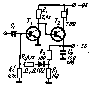
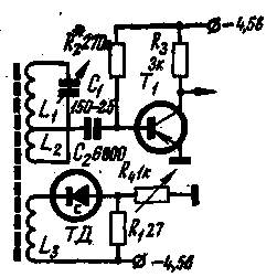
The total number of turns in the coil L1 is preserved, and for connection with the tunnel "diode, a winding L1 is wound on top of L2 from the side of its grounded end, containing 10 turns of PELSHO 0,15 wire. The connection winding with the converter L3 remains approximately the same, but for the greatest sensitivity, the number of turns The capacitances of capacitors C1 and C2 remain unchanged, The tunnel diode is powered from a common source.In this case, the resistance R2 should be equal to 1,2 kΩ.The tunnel diode should be selected with a maximum current of no more than 1,5 mA. It is more rational for apply the above-mentioned stabilization circuit with the help of a transistor to power the diode.For this, the LF amplifier is redone according to the circuit shown in Fig. 4. A DC connection is introduced between the transistors of the LF amplifier.The bias to the base of the transistor T1 is removed from the emitter of the transistor T2 through the R4D1 circuit, and resistances R2, R3. The resulting negative current feedback maintains the emitter current, and hence the voltage across the resistances R2 and R3, almost constant when the supply voltage is reduced by 25-30% of the nominal value (it is better to increase the supply voltage to 9 B).
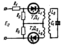
To power the tunnel diode, a voltage of 2 V is used, supplied to the divider through the resistance R2 (Fig. 3), which in this case is taken to be 430 ohms. The adjustment begins with checking how the voltage at the emitter of the transistor T2 changes when the supply voltage decreases from 6 to 4,5 V or from 9 to 6 V. If the voltage changes by no more than 5-10%, then setting the supply voltage equal to 5,2 V (or 7,5 V at 9 V), go to the generator setting. To do this, the rotor of the variable capacitor C2 is placed in the middle position and, by adjusting the resistance values R1 or R2 (Fig. 3), the maximum oscillation amplitude is achieved. Then check the uniformity of generation over the entire range. If oscillations fail in any of its sections, the winding of the L2 coil should be increased by several turns and the uniformity of generation should be checked again during the restructuring. Having finished tuning the local oscillator, select the number of turns of the local oscillator connection winding with the L3 converter until the optimal sensitivity is obtained. When designing generators based on tunnel diodes, one should strive to obtain the maximum quality factor of the oscillatory circuit in order to increase the power delivered to the load. To increase the power, you can also include two or more diodes in the oscillator circuit. In this case, as follows from the consideration of the energy ratios, it is advantageous to connect the diodes in direct current in series. Then the voltage at the lower resistance of the divider will be twice as high as for one tunnel diode, and the losses on the upper arm will decrease. It must be borne in mind that the resistance of the lower arm must necessarily consist of two identical resistances, and their midpoint must be connected by direct current to the midpoint of two diodes (Fig. 5). Otherwise, stable operation of two diodes connected in series is impossible. For alternating current, diodes can be connected in parallel or in series. In the diagram shown in fig. 5 each diode is connected to a separate winding. To get the most power, the coupling of each tunnel diode to the loop must be adjusted individually.
Tunnel diodes can also be used in aperiodic amplifier circuits. However, as indicated in the literature, such aperiodic amplifiers in the ranges of long and medium waves are not very practical due to the difficulty in separating the load and the signal source. It should also be taken into account that transistors, with comparable power consumption, have a large gain in real circuits compared to tunnel diodes. Resonant tunnel diode amplifiers are relatively easy to build. They can be performed, for example, according to the oscillator circuit, in which the feedback coefficient is insufficient to excite oscillations. Such schemes have all the disadvantages of regenerative amplifiers: instability of the regeneration threshold, the possibility of excitation when the load changes, narrowing the bandwidth with increasing gain. However, such amplifiers can work quite stably if you do not strive to get maximum gain from them. A circuit with this use of a tunnel diode is shown in fig. 6. The figure shows a diagram of the input part of a direct gain receiver with a ferrite antenna. It is known that in order to match the resistance of the antenna circuit with the input resistance of the transistor, the transformation ratio of the transformer formed by the windings of the coils L1 and L2 is much less than one.
This leads to the fact that the signal voltage at the base of the transistor turns out to be 15-20 times less than the voltage on the L1C1 circuit. In the diagram shown in Fig. 6, the coupling coefficient is chosen much more than usual and the tap to the base of the transistor T1 is made from 1/5 of the total number of turns of the coil L1. In this case, the L1C1 circuit turns out to be heavily shunted, its band expands and the receiver sensitivity drops. However, when the tunnel diode is connected to the additional winding L3, the circuit is partially “unloaded”, its attenuation and bandwidth return to normal. In this way, it is possible to obtain a gain in the sensitivity of the receiver by a factor of 4-5. The number of turns of the winding L3 is chosen so that the attenuation of the circuit is not fully compensated, and the amplifier is not excited. However, to get maximum sensitivity, you need to get as close to the drive threshold as possible, so the bias of the tunnel diode is made adjustable. The winding of the L1 coil contains 200 turns of PELSHO 0,15 wire, wound in one layer turn to turn on a ferrite rod 110 mm long, 8,4 mm in diameter with a tap from 44 turns. The winding of the L3 coil contains 8-10 turns of PELSHO 0,15 wire, it is wound near the grounded end of the L1 coil. The disadvantage of the proposed scheme is that the input circuit overlap coefficient decreases, since due to the increased coupling coefficient, the input capacitance of the transistor T1 will have a stronger effect. In addition, the recalculated capacitance of the tunnel diode will be added to the capacitance of the circuit. Therefore, if a sufficiently large overlap is required, it is advisable to use a tunnel diode with a minimum capacitance. It is more advantageous to use regenerative amplifiers for a fixed frequency, for example, in a superheterodyne IF amplifier (Fig. 7). To do this, an additional winding for a tunnel diode is wound on one of the IF circuits. It is better to make the bias of the diode stabilized. This will allow you to get close enough to the regeneration threshold and get a 8-10 times gain in gain. It must be taken into account that the bandwidth of the IF amplifier narrows sharply if the inclusion of the tunnel diode was not foreseen in advance. In some cases, when a diode is connected, the amplifier may be excited, although the coupling coefficient is insufficient for generation. This is because the gain of the cascade with the tunnel diode connected becomes greater than the maximum stable value.
During installation, it must be taken into account that tunnel diodes are prone to excitation on parasitic reactances. Therefore, the conclusions of the diode and related parts are made of a minimum length, and the installation is carried out as if the circuit was intended to operate at very high frequencies. Do not use tunnel diodes with a high cutoff frequency in low-frequency circuits. When experimenting with tunnel diodes, current and voltage surges must be avoided, otherwise the diode may fail. Connect and disconnect the diode only when the power is off. Literature
Author: V.Morozov; Publication: N. Bolshakov, rf.atnn.ru
Traffic noise delays the growth of chicks
06.05.2024 Wireless speaker Samsung Music Frame HW-LS60D
06.05.2024 A New Way to Control and Manipulate Optical Signals
05.05.2024
▪ Eternal batteries based on nanodiamonds and radioactive waste ▪ Children learn kindness from human stories ▪ Temple air is dangerous to health
▪ section of the site Cultivated and wild plants. Article selection ▪ article by Aristippus of Cyrene. Famous aphorisms ▪ article Do animals have a sense of taste? Detailed answer ▪ article Banana textile. Legends, cultivation, methods of application ▪ article Automatic charger. Encyclopedia of radio electronics and electrical engineering ▪ article Smoke without fire. Chemical experience
Comments on the article: Sergei I read the first publication about communication with a transmitter based on a low-power tunnel diode in the 3,5 MHz range, a distance of 240 kilometers (if memory does not fail) in the Radio magazine (section Abroad) somewhere in the early 60s. I did not find a diode then, for the experiment I assembled a single-transistor "beacon" for the same 3,5 MHz. It turned out the audibility of the signal at distances of 20 ... 60 km. It was not possible to continue the experiment at a greater distance, it began to get dark and distant powerful stations began to interfere.
Home page | Library | Articles | Website map | Site Reviews www.diagram.com.ua |


 Arabic
 Bengali
 Chinese
 English
 French
 German
 Hebrew
 Hindi
Hindi Italian
 Japanese
 Korean
 Malay
Malay Polish
 Portuguese
 Spanish
 Turkish
 Ukrainian
 Vietnamese
 Leave your comment on this article: