
|
|
ENCYCLOPEDIA OF RADIO ELECTRONICS AND ELECTRICAL ENGINEERING Proportional control equipment. Encyclopedia of radio electronics and electrical engineering
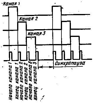
Encyclopedia of radio electronics and electrical engineering / Radio control equipment The equipment for proportional control of models is manufactured by many foreign companies. Basically, this is a pulsed multi-channel equipment, equipped with steering gears. Its circuit solutions may well be used for the manufacture of equipment in amateur conditions. Well-known Czech design engineer V. Valenta did just that. He took the equipment of the "Teleprop" system as a basis, made the necessary changes to it and produced his own, modernized version. The description of this equipment will acquaint the reader with how one of the principles of building a pulsed multichannel proportional control radio link is implemented in practice. The peculiarity of this system is that when transmitting information about the position of the control knobs of the command sensors to the radio-controlled model, pulse-width modulation (PWM) with time division of control channels and synchropause is used (Fig. 1). The modulating signal is formed by clock (T=20 ms) and multiphase adjustable multivibrators, differentiating circuits, diode summing cells and output single vibrator.
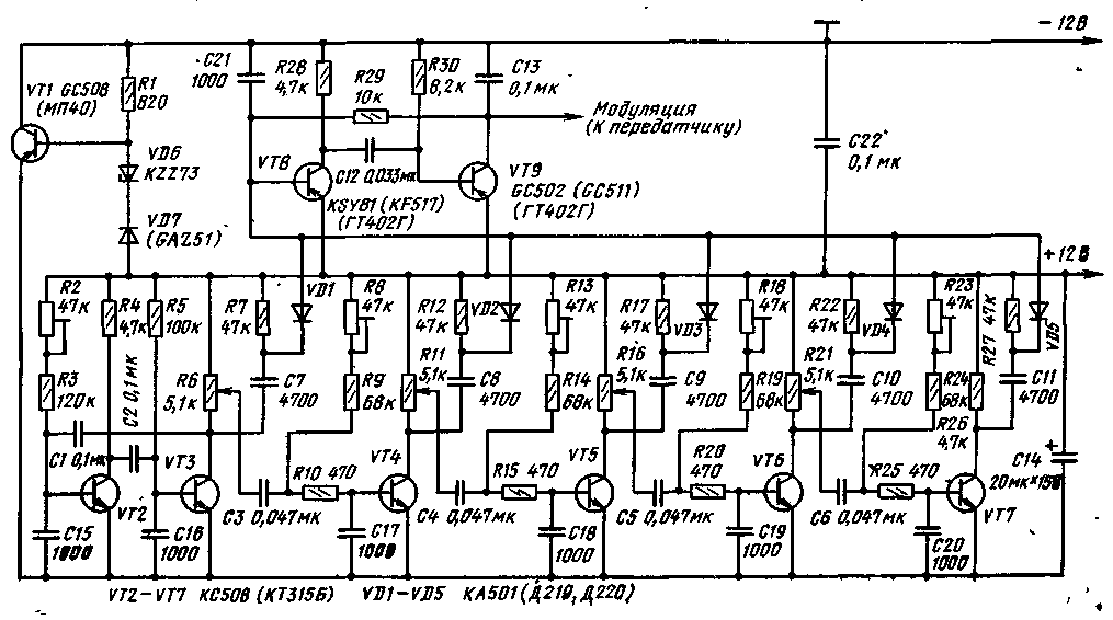
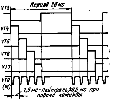
On fig. 2 shows a schematic diagram of a four-channel encoder. The multivibrator on transistors VT2, VT3 starts a multi-phase multivibrator, the transistors VT4-VT7 of which are open by the base current through resistive circuits. Let us assume that at the initial moment of time the transistor VT3 is closed. Capacitor C3 is charged to a certain voltage, depending on the position of the variable resistor R6. When switching the multivibrator, the transistor VT3 will open and the voltage of the capacitor C3 will close the transistor VT4. Transistor VT4 will be closed until the capacitor C3 is discharged through the circuit R8, R9. Thus, the switching time of the transistor VT4 depends on the position of the variable resistor R6 slider connected to the control lever of the command sensor, and on the position of the trimmer resistor R8 slider, which sets the pulse width at the neutral position of this lever. Differentiating circuits C3, R7, C7, R7, etc. are connected to the collector of transistors VT8-VT12, connected through diodes VD1-VD5 to the assembly line. A signal is formed on it, consisting of a synchropause and differentiated short pulses that occur at the beginning and end of the channel interval. Diagrams of the collector voltage of the encoder transistors are shown in fig. 3.
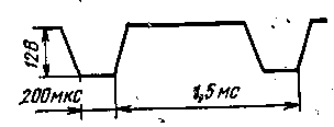
The transmitter's modulating transistor works like a switch, which, in rhythm with the modulation, connects the supply voltage to the output stage. Since the narrow pulses on the combined line (Fig. 4) have different durations due to the spread in the values of the elements of the differentiating circuits, the modulator generates a modulating signal in the form of pulses with certain parameters. For this purpose, a single vibrator based on transistors VT8, VT9 (Fig. 2) is designed, the time constant of which is chosen according to the pulse duration. Transistor VT9 also serves as a modulator.
To establish an encoder, an oscilloscope with time base calibration is required. A battery with a voltage of 12 V is connected to the encoder. Collector voltage diagrams are checked using an oscilloscope (Fig. 3). The trimming resistor R2 sets the required duration of the multivibrator period (20 ms). The duration of each channel pulse in the neutral position of the command transmitter lever should be 1,5 ms. When the command transmitter lever is moved to the extreme positions, the duration of the channel pulse changes by +0,5 or -0,5 ms, respectively. Thus, the limits for changing the pulse duration are 1-2 ms. Trimmer resistors R8, R13, R18, R23 set the required pulse duration in each channel with the lever in neutral position. The sliders of variable resistors R6, R11, R16 and R21 are mechanically connected to the levers in the command transmitter of the transmitter. Next, the voltage on the combined line is controlled by the oscilloscope. The collector of the transistor VT9 through a resistor with a resistance of 100 ohms is temporarily connected to a common wire (with the negative terminal of the power source). The voltage diagram should correspond to Fig. 5. Capacitor C13 is designed to give the pulses of the modulating signal a trapezoid shape.
This pulse shape reduces the level of harmonics in the high-frequency signal, narrows the emission band and increases the output power of the transmitter. If the pulse duration differs from 200 μs, then it is changed by selecting the capacitor C12. The closing resistor with a resistance of 100 ohms is removed - the encoder can be connected to the transmitter. The master oscillator of the transmitter (Fig. 6) is made according to the scheme with quartz frequency stabilization. The connection between the steps is inductive. A P-filter C5, L4, C6 is connected to the collector of the output stage transistor, which effectively suppresses harmonic components. Coil L5 - matching. The recommended antenna length is 1400 m. The following domestic transistors can be used in the transmitter: VT1 - KT315-KT316 series; KT306A- KT306V, KT603; VT2 - KT603 series. KT904A, KT606A.
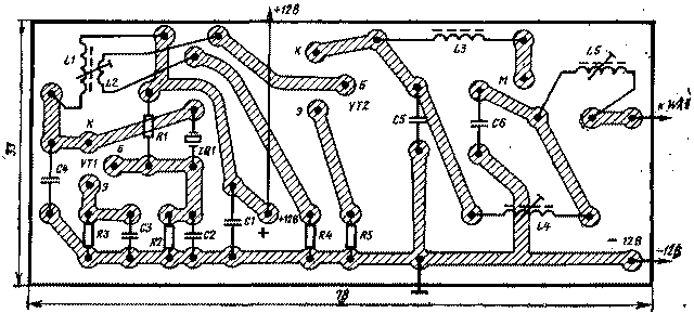
The coils have the following characteristics: L1 - 14 turns of wire PEV-2 0,8 on a frame with a diameter of 8 mm with a ferrite trimmer 10 mm long; L2-5-6 turns of mounting wire with a diameter of 0,8 mm. in PVC or PTFE insulation, L2 is wound over L1; L4-7 turns of wire PEV-2 0,8 on the same frame as L1; L5 -19-25 turns of PEV-2 0,3 on the same frame (the number of turns is selected depending on the length of the antenna used). A quartz resonator is used at a frequency of 27,12 MHz ± 0,05%. It is recommended to test the transmitter with the antenna fully deployed. When operating the transmitter without an antenna, thermal overload of the terminal transistor is dangerous. The "extension" coil L5 of the antenna, if used, is tuned to the field strength indicator. The transmitter housing is connected to a common wire at one point. On fig. 7 shows a drawing of the printed circuit board of the transmitter. The board is shown from the side of the details. To power the transmitter, a battery of ten nickel-cadmium batteries TsNK-0,45 or TsNK-0.9U2 is used. Three 3336 batteries connected in series can serve as a backup power source.
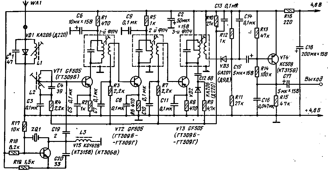
Finally tune the transmitter after installing it in the housing. At the same time, the "extension" coil of the antenna is adjusted, while the transmitter must be in hand. The transmitter power is approximately 500 mW. It is recommended to install the terminal transistor of the transmitter on a heat sink. The onboard part of the equipment contains a receiver, a decoder, four identical servo amplifiers and steering machines. The receiver is a superheterodyne tuned to a fixed frequency. To ensure tuning-free. connections of the receiver local oscillator are assembled according to the oscillator circuit with quartz frequency stabilization. The receiver circuit is shown in fig. 8. At the input of the receiver, a band-pass filter is used that separates the antenna from the input transistor VT1. This increases the selectivity and reduces the return radiation of the local oscillator to the antenna, allows using any high-frequency channel within the frequency limits allocated for radio control of models without restructuring the input circuits, by simply replacing the quartz resonator. In this case, the frequency difference between adjacent channels can be equal to 0,01 MHz.
The local oscillator operates at a frequency that is lower than the frequency of the received signal by 465 kHz. Diode VD3 serves as a signal detector, and VD2 serves as an AGC signal detector. The signal voltage for the AGC is taken from the primary winding of the intermediate frequency transformer (intermediate frequency transformers V. Valenta calls intermediate frequency filters, which are single circuits with a coupling coil) and rectified by a silicon diode, which simultaneously determines the operating point of the mixer and intermediate frequency amplifier transistors. The precise operation of the AGC system is important, mainly at small distances of the receiver from the transmitter. The receiver is designed for the use of finished parts, including intermediate frequency transformers. The intermediate frequency can be between 455 and 468 kHz. An indicator of the quality of a high-frequency transformer is the quality factor. It should be equal to 120-140. The bandwidth of the received signal is 8-10 kHz. The receiver should be mounted on one board. Installation can be anything. Coil frames L1 and L2 have a diameter of 5 mm. Adjust the coil with ferrite cores, the distance between the axes of the coils is 9 mm (it is necessary to strictly maintain this distance). The coils are wound with wire PEV-2 0,3; L1 contains 10 turns, and L2-13 turns with a tap from the third turn, counting from the end grounded through the capacitor C3. The high-frequency inductor L3 is wound on an insulating frame with a diameter of 3 mm and a length of 11 mm with a PEV-2 wire 0,06 turn to turn until filled. The inductor can also be wound on a resistor MLT-0,5 with a resistance of at least 100 kOhm. Establishing the receiver is to configure the input bandpass. filter and intermediate frequency transformers. The author recommends tuning the receiver according to the signals of the transmitter with a shortened antenna. If you tune the receiver from a standard signal generator, you must know the frequency of the transmitter very accurately and tune the generator to it. Before tuning, an antenna 1 m long is connected to the receiver, and high-impedance telephones are connected to the output. First, the input filter L1C1 is adjusted and, as the sensitivity increases, the transmitter is removed to such a distance that the signal in the phone is weakly heard, and the maximum is again achieved during tuning (including by specifying the mode of the VT4 transistor). Then adjust the intermediate frequency transformers. The receiver decoder circuit is shown in fig. 9. Diode VD1 is designed not to miss an interference signal with an amplitude less than the direct voltage drop across it, i.e., about 0,6 V. The amplitude of the useful signals coming from the output of the receiver is approximately 1,1 V.
The useful signal is fed to the base of the transistor VT1, which operates as an inverter. Transistors VT2 and VT3 are pulse shaper amplifiers. Transistor VT4 is closed in the absence of a signal, and capacitor C6 is charged to full supply voltage. The first pulse will open the transistor VT4 and discharge this capacitor. On transistors VT5 and VT6, a Schmitt trigger is assembled, which periodically opens the transistor VT7, and it, in turn, at these moments passes clock voltage pulses to the assembly line. Transistors VT8, VT10, VT12, VT14 are part of the shift register triggers. Through the VD2 diode, the first trigger of the register is launched. Diagrams of the collector voltage on the decoder transistors and the shape of the channel pulses on. emitters of transistors VT9, VT11, VT13, VT15 are shown in fig. 10. The shift register on transistors of various structures is very simple and quite competitive in comparison with the register on transistors used by a number of foreign firms. The decoder should use transistors with coefficient h21e>50.
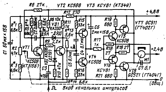
Setting up a decoder is easy. First, resistor R3 is selected so that the collector of transistor VT1 has a voltage of 1,5-2,5 V. The resistance of the resistor is changed in the range of 430-820 kOhm. The final link of the on-board equipment is the electronic steering gear unit. The system used steering - machines "Varioprop". Schematic diagram of the electronic unit of the steering machine is shown in fig. 11. The purpose of the block is to convert the duration of the pulses coming from the decoder into a mechanical deflection of the steering gear lever, proportional to the duration of the channel pulse, which in turn is proportional to the deflection of the command sensor lever. A single vibrator assembled on transistors VT1 and VT2 and triggered by the front of the input channel positive pulse generates a pulse of negative polarity. Both pulses - a positive channel and a negative single vibrator are fed through resistors R13 and R14 to point A for comparison.
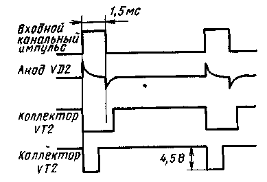
When the single vibrator is started and the steering gear lever is in neutral position, a negative pulse with a duration of 2 ms arrives at point A from the collector of transistor VT1,5. The pulse duration of the single vibrator is regulated by a variable resistor R2, the engine of which is mechanically connected to the output shaft of the steering machine. As a result of the comparison, short pulses are generated, the polarity of which depends on the direction of movement of the command transmitter lever from the neutral position. With the same duration of the compared pulses, the signal to the input of the DC amplifier that feeds the steering machine does not arrive, so the steering motor shaft does not rotate. Let us consider the case when the single vibrator pulses are narrower than the channel pulses. After subtraction, we obtain positive pulses, the duration of which is the smaller, the smaller the difference in the duration of the compared pulses. Positive pulses open the key on the transistor VT4 and charge the integrating capacitor C6 with a negative voltage relative to the midpoint of the power supply, which is supplied to the DC amplifier on transistors VT6, VT8. The electric motor M1 turns on and, through the reduction gear, moves the rudder shaft and the associated variable resistor R2 engine down the circuit. The duration of the positive pulse of the single vibrator increases and, when it equals the duration of the channel pulse, the voltage at point A will become equal to zero. Transistor VT4 will close, capacitor C6 will discharge to half the supply voltage, transistors VT6 and VT8 will close, the engine will stop. However, a system containing integrating links (capacitor C6 and an electric motor of a steering machine) has inertia. Therefore, the engine must be switched off a little earlier than the moment when the compared pulses become the same. For this, negative feedback is introduced, since otherwise mechanical oscillations of the output shaft of the steering machine will begin. The negative feedback voltage from the output of the steering servo amplifier is applied to the input of the single vibrator through resistors R6 and R8. In the case when the single vibrator pulse has a longer duration than the channel pulse, negative pulses are formed at point A. They open the key on the transistor VT3, the capacitor C6 is charged positively with respect to the front point of the power supply, the transistors VT5 and VT7 open, and the motor rotates in the opposite direction, moving the variable resistor R2 upwards in the circuit. As soon as the input channel pulse is equal in duration to the single vibrator pulse, the rotation of the steering motor shaft will stop. Resistor R12 and capacitor C1 form a filter in the power supply circuit of the single vibrator, which is necessary for decoupling the power circuits of single vibrators, since during the operation of steering machines, the current drops, and hence the fluctuations in the supply voltage, are significant. This leads to a change in the parameters of the single vibrator pulses and violates the proportionality of the deviation of the transmitter lever in the steering machine. The advantages of the described electronic unit in comparison with analog ones include the fact that the final amplifier operates in the key mode, open or closed. The time during which the amplifier is in the closed or open state depends on the amplitude of the integrated sawtooth voltage. As soon as the difference in the pulse durations of the channel and the single vibrator starts to approach zero, the amplitude of the sawtooth voltage will become minimal. At the same time, pulses of short duration are supplied to the electric motor, and, slowing down, it brings the steering wheel to the desired position. The considered principle is widely used in the creation of proportional control equipment. Circuit solutions are very diverse, for example, the method of starting a single vibrator, including a variable resistor in mechanical feedback, changing the polarity or amplifying the input channel pulse, replacing the amplifier on transistors VT5, VT6 with a Schmitt trigger, etc. The electronic unit of the steering machine is mounted on a separate board. All elements are placed on it, except for the variable resistor R2 and the electric motor M1. Consider the process of establishing an electronic steering gear unit. A selection of resistors R1 and R3 set the maximum turn of the steering gear lever. In this case, it is convenient to use the control signals of the transmitter. The input of the electronic unit is connected to the decoder. Flexible conductors connect the outputs from the variable resistor R2 and the electric motor to the board. Turn on the power, but leave the middle terminal of the batteries free for now. The steering lever is set to the neutral position. Temporarily, instead of resistor R4, a variable resistor with a resistance of 47k0m is connected. On the oscilloscope screen, voltage diagrams are observed at individual points. They must match Fig. 12.
Then connect the oscilloscope to point A and observe the voltage waveform shown in Fig. 13, a-d. The decoder should receive pulses corresponding to the neutral position of the command transmitter lever. The duration of these pulses is 1,5 ms.
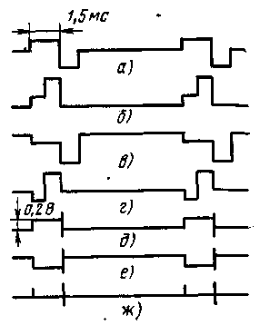
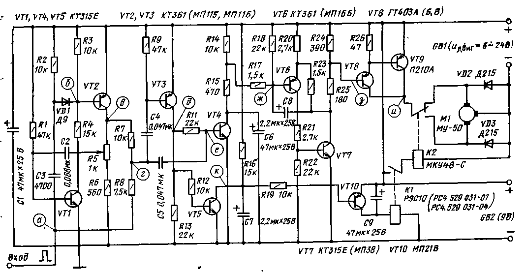
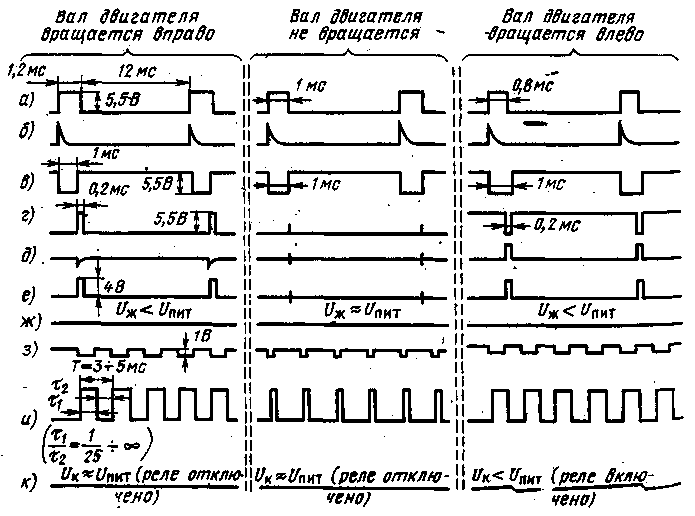
With a variable resistor included instead of R4, such a bias voltage is set at the base of transistor VT1 so that at point A the signal shape corresponds to Fig. 13, a or f. When choosing resistors R13 or R14, it is necessary to ensure that the voltage surge is observed only at the beginning and end of the channel pulse (Fig. 13). Having measured the resistance of the variable resistor corresponding to this case, a constant resistor R4 with the same resistance is soldered onto the board. Now connect the middle terminal of the battery. At the same time, the servo motor must remain in the neutral position, and when the command changes, i.e., when the command transmitter lever of the transmitting device is moved, it must rotate evenly. Transistors of the pnp structure in the DC amplifier should be used with the base current transfer coefficient h21e> 80. PROPORTIONAL SPEED CONTROL WITH BUS MOTOR Most auto and boat models are driven by electric motors. The development of model technology of proportional control made it possible to solve the problem of reversing the running electric motor and smooth regulation of the frequency of rotation of its shaft in both directions. Smooth control of the speed of movement makes it possible to carry out the model accurately on difficult routes. Consider one of the options for proportional control of the speed of the travel motor. The electronic unit of this peculiar mechanism converts the duration of the channel pulses into the speed of the shaft of the travel motor and ensures its reversal. To control such a unit, pulse systems of proportional multi-channel radio control are suitable, in which the duration of channel pulses is in the range from 1 ± 0,5 to 2 ± 0,5 ms. The amplitude of the channel pulses should be 4-9 V. The diagram of the control unit for the frequency of rotation of the motor shaft is shown in fig. one. The unit is reliable in operation, its feature is the absence of feedback. Channel pulses of positive polarity are fed from the decoder to the block input. The pulses after differentiation by the capacitor C3 by the front start a single vibrator on transistors VT1, VT2. On the collector of the transistor VT2 (point c), pulses of negative polarity calibrated in duration are formed. Voltage diagrams at different points of the block are shown in fig. 2. They were taken for the case of supplying the unit with a voltage of 6 V and the electric motor - 12 V. The duration of the channel pulse is 1 ms and changes during the control by ±0,2 ms.
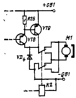
The input channel pulse and the single vibrator pulse at point r are added. If the resulting pulse is positive, then passing through the capacitor C5, it will open the transistor VT4 of the integrating stage and change the voltage at the base of the transistor VT6. A multivibrator is assembled on transistors VT6 and VT7. Changing the mode of the transistor VT6 causes a change in the frequency and duration of the generated pulses. If, however, the resulting pulse at point r is negative, then it is inverted by the cascade on the transistor VT3 and also opens the transistor VT4. Rectangular pulses from the multivibrator are fed to a power amplifier based on transistors VT8, VT9. The collector circuit of the transistor VT9 includes a running motor, the shaft speed of which depends on the frequency and duty cycle of the pulses. The output transistor of the power amplifier operates in the key mode, the losses on it are negligible. If the amplitude of the channel pulse and the single vibrator pulse are equal, the engine will stop. As the stress diagram shows. point and, the engine is not completely de-energized, but the power on it does not exceed fractions of a watt. If the total impulse at point r becomes negative, the direction of rotation of the motor shaft will change (there will be a reversal). The travel motor is switched on by the contacts of the relay K3, which is activated after the operation of the intermediate relay K1, which is the load of the transistor VT10. The integrating capacitor maintains a constant voltage at the base of the VT10 transistor when positive pulses appear at the base of the VT5 transistor. Capacitor C9 smooths the voltage across the transistor VT10 and prevents the contacts of relay K1 from rattling. On fig. 3 shows a variant of the circuit for switching on a travel motor with excitation from a permanent magnet.
Adjust the block using an oscilloscope. The process starts from the control node. It is necessary to ensure that the ratio of the duration of the pause to the duration of the output pulses of the multivibrator changes when the width of the input channel pulse changes. The output transistor should be completely off. A voltmeter is connected between the emitter and collector of the transistor VT9. Its reading should be close to zero at maximum motor voltage. If the transistor VT9 t opens completely, it should be replaced with another one with a higher value of the coefficient h21e, or the transistors VT6-VT8 should be replaced with others with a higher value of this coefficient. Then they achieve a clear operation of the relay K1. If it does not work at the minimum voltage on the motor, then you should select transistors VT5 and VT10 with a large value of h21e, and also clarify the resistor values in their base circuits. With a motor load current of up to 4 A, you can choose R25 with a resistance of 300 ohms; R26-390 Ohm; -VT8 - from the MP16 series; VT9 - from the P214 series - P217, P4. The reliability of the unit when controlling powerful electric motors can be increased by using two transistors instead of one VT9, connected in parallel and installed on heat sinks. Literature
Publication: N. Bolshakov, rf.atnn.ru
A New Way to Control and Manipulate Optical Signals
05.05.2024 Primium Seneca keyboard
05.05.2024 The world's tallest astronomical observatory opened
04.05.2024
▪ Empathy and synchronous oscillations of neurons ▪ Vaccination against hypertension ▪ Tunguska meteorite - once in a thousand years
▪ section of the site Electrician's Handbook. Article selection ▪ article Electric cultivator. Drawing, description ▪ article Which country is located on the Hindustan Peninsula? Detailed answer ▪ article Dislocations. Health care ▪ article Bird's trick. physical experiment
Home page | Library | Articles | Website map | Site Reviews www.diagram.com.ua |


 Arabic
 Bengali
 Chinese
 English
 French
 German
 Hebrew
 Hindi
Hindi Italian
 Japanese
 Korean
 Malay
Malay Polish
 Portuguese
 Spanish
 Turkish
 Ukrainian
 Vietnamese




 Leave your comment on this article: