|
|


 Arabic
 Bengali
 Chinese
 English
 French
 German
 Hebrew
 Hindi
Hindi Italian
 Japanese
 Korean
 Malay
Malay Polish
 Portuguese
 Spanish
 Turkish
 Ukrainian
 Vietnamese
|
ENCYCLOPEDIA OF RADIO ELECTRONICS AND ELECTRICAL ENGINEERING Portable radio stations for 1215 ... 1250 MHz. Encyclopedia of radio electronics and electrical engineering
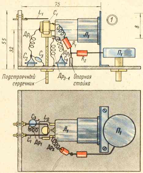
Encyclopedia of radio electronics and electrical engineering / Civil radio communications Radio station on a 12C3C lamp Scheme and details. The radio station was assembled on 12C3S and 6Zh9P lamps according to the transceiver circuit (Fig. 1). To reduce the influence of the inductance of the terminals and elements of the L1 lamp, the L1 circuit is attached directly to its terminals and, as it were, is their continuation. The radio station is tuned using a cylindrical brass core with a diameter of 6 mm and a height of 6 mm. Communication with a corner antenna is inductive, through a loop of connection L1.
The antenna and radio station blocks are mounted on a common wooden rail. To reduce losses, the high-frequency unit is attached directly to the antenna and is covered with a Plexiglas casing. This block is assembled on a 2 mm thick duralumin panel measuring 200x80 mm. The location of the parts of the RF block is shown in fig. Particular attention must be paid to the execution of the brass core, which must have reliable contact with the body and minimal play. All circuit elements are rigidly fixed on the panel.
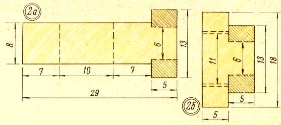
The L2 contour is made of silver-plated sheet 0,2-0,4 mm thick. On fig. 2, a is a drawing of half of the circuit connected to the anode of lamp L1, and in fig. 2, b - drawing of a half connected to its grid. The areas shaded in the figure are bent and crimped around the corresponding terminals of the lamp, making reliable contact.
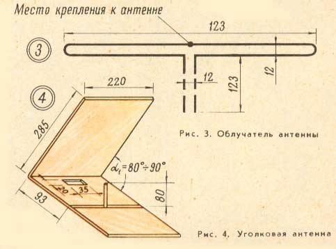
Capacitor C1 is an integral part of the circuit. It is performed as follows. The petals of the grid half of the contour are bent along the lines indicated by the double dotted line and crimped around the free end of the anode half. Before that, between the halves, it is necessary to install a gasket made of mica or fluoroplastic with a thickness of 0,1-0,3 mm. Inductors Dr3,4,5 are connected to the terminals of the lamp as follows: the end of the inductor is wound around the lamp leg (3-4 turns), then removed and twisted slightly. The resulting turns with friction are put on the lamp leg. The connection loop L1 is made of silver-plated wire with a diameter of 1,5-2,0 mm and has dimensions of 30x12 mm. The optimal distance between the connection loop and the L2 circuit is selected during tuning. Inductors Dr2,3,4,5 are made of silver-plated wire with a diameter of 0,3-0,6 mm and contain three turns with a diameter of 5 mm; winding length - 10 mm. Choke Dr1 is made of silver-plated wire with a diameter of 2 mm. It contains three turns. Choke diameter - 5 mm, winding length - 10 mm. Throttle Dr6 - low-frequency from a telephone set. Transformer Tr1 of any type, designed to work with a carbon microphone. The antenna feed and feeder are made of copper wire with a diameter of 2 mm (Fig. 3).
The antenna frame consists of aluminum tubes with a diameter of 4-6 mm. The frame is covered with a metal mesh (Fig. 4). The irradiator is mounted on a wooden or metal stand located on the lower plane of the antenna. Feeder irradiator passes through a rectangular hole in the antenna and is connected to the loop L1. The HF unit and the irradiator are mounted in such a way as to provide a feeder length of 123 mm. Capacitors C2 and C8 are through. They are attached to the corners. Capacitor C3 - type KDK. It is advisable to choose a new lamp L1 (not used). Lamp L2 can also be used type 6Zh5P. Setting up a radio station starts with checking the correct installation. Then you need to turn on the milliammeter in the anode circuit. In transmission mode, the anode current should not exceed 30 ml. The presence of generation can be determined by touching a screwdriver with an insulated handle to the grid terminal. At the atom. the anode current should increase. Having achieved generation, one should begin to determine the limits of frequency tuning. For this, a conventional measuring line is used. In the receiving mode, the anode current of the L1 lamp should not exceed 20 mA. It is necessary to achieve the appearance of stable super-regenerative noise by changing the capacitance of the capacitor C3 or the resistance of the resistor R3. The point of connection of the inductor Dr1 to the circuit is determined by moving the end of the screwdriver along the circuit L1. The place where generation disruption is not observed (maximum noise in the receive mode), and will be this point. Antenna tuning and the choice of the transceiver connection value with the feeder is made according to the field strength indicator located at a distance of 5-7 m from the antenna. The antenna is tuned by changing the opening angle. The radio station was tested for communication in stationary and field conditions. Communications at a distance of up to 12 km were carried out with RSM 575-585. Radio station on the lamp 6S21D Scheme and details. The diagram of the RF block of the radio station is shown in Fig. 4. Its design is much simpler; in addition, it has better technical data compared to a radio station on a 12C3C lamp. For its manufacture, two sets of circuits with 6S21D (6S11D) lamps are required.
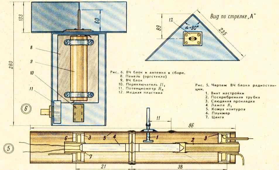
Both generators are dismantled. The silver-plated casings of circuits 5 are joined end-to-end (see Fig. 5). The anode terminal of the lamp is lengthened. To do this, the outer side of the plunger 6 of the second set is heated with a soldering iron, collet 7 is removed from it. Then the collet is shortened to 10 mm and butt-soldered to a silver-plated tube with a diameter of 6 mm and a length of 35 mm. The adjustment screw is moved by 11 mm and lengthened by 30 mm. The tuning knob and resonator must be isolated from the body. A tube with a soldered collet is put on the anode of the lamp. The assembled generator is fixed with clamps on a Plexiglas panel.
To match the antenna with the circuit, the output of the communication coil is extended by 60 mm with a silver-plated wire with a diameter of 2 mm, which serves as an antenna feed. Two copper plates 2x18 mm in size are soldered to the output tube on both sides, which, during assembly, are soldered to copper plate 12 (Fig. 6) 20x35 mm in size. The latter is attached to the base of the antenna and isolated from it with a mica gasket 0,1-0,3 mm thick. The antenna is assembled from duralumin plates. Chokes Dr2,3,4 have 3 turns of PE 0,5 wire. Winding length - 13 mm, diameter - 5 mm. Choke Dr1 contains 270 turns of PELSHO 0,1 wire and is wound on a frame with a diameter of 5 mm. Phones are used high-resistance. Their resistance is 2,2 com. The modulator can be of any design. The power of the modulator is 1-1,5 watts. Radio station tuning Please note that the voltage applied to the lamp anode must not exceed 120 V, otherwise the lamp life will be significantly reduced. The setting begins with the fact that in the transmission mode, the presence of generation is determined by the field strength indicator. By moving the cathode plunger, maximum power is achieved (control - according to the field strength indicator). The radio is then turned on for reception. By selecting the value of the capacitance C1, one achieves the appearance of stable super-regenerative noise. The radio station was tested for communication in the 1967 Field Day competition and showed good results. Communication at a distance of up to 12 km took place with RSM 595 in both directions. Authors: A. Bondarenko (UA3TEG), N. Bondarenko (UA3TED); Publication: N. Bolshakov, rf.atnn.ru
A New Way to Control and Manipulate Optical Signals
05.05.2024 Primium Seneca keyboard
05.05.2024 The world's tallest astronomical observatory opened
04.05.2024
▪ Bees warn each other of danger ▪ The existence of a time loop has been proven ▪ Airplane powered by steam jet
▪ section of the site The most important scientific discoveries. Article selection ▪ Article Law of Conservation of Energy. History and essence of scientific discovery ▪ article How did the Moscow Textile Academy come about? Detailed answer ▪ Daikon article. Legends, cultivation, methods of application ▪ article Light for a minute. Encyclopedia of radio electronics and electrical engineering
Home page | Library | Articles | Website map | Site Reviews
www.diagram.com.ua |


 Leave your comment on this article: