|
|


 Arabic
 Bengali
 Chinese
 English
 French
 German
 Hebrew
 Hindi
Hindi Italian
 Japanese
 Korean
 Malay
Malay Polish
 Portuguese
 Spanish
 Turkish
 Ukrainian
 Vietnamese
|
ENCYCLOPEDIA OF RADIO ELECTRONICS AND ELECTRICAL ENGINEERING Radio station at 430 ... 440 MHz. Encyclopedia of radio electronics and electrical engineering
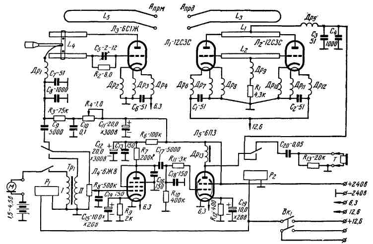
Encyclopedia of radio electronics and electrical engineering / Civil radio communications The described radio station is structurally quite simple and does not contain scarce parts. Its construction is available to a wide range of radio amateurs who want to direct their efforts to mastering the 70-cm range. The radio station can be powered from a power unit containing a rectifier, or from a battery and galvanic batteries. scheme Schematic diagram of the radio station is shown in fig. 1. It consists of a transceiver and a power supply. The radio station is made according to the transceiver scheme. The transmitter is assembled on lamps L1 and L2 - VHF triodes 12C3C. It can also use double triodes of the 6N15P type (the electrodes are connected in parallel). The transmitter uses a push-pull oscillator circuit. It is simple to perform and establish, reliable in operation and quite economical in terms of power. Some of the disadvantages inherent in such an oscillator (low frequency stability and the presence of spurious frequency modulation) are not of particular importance, since the receivers currently used by radio amateurs for these frequencies are made mainly according to a simple super-regenerative circuit and have a wide bandwidth.
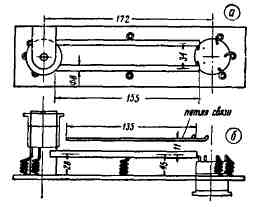
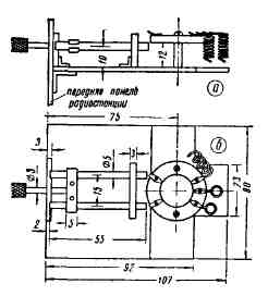
The oscillatory circuit of the autogenerator consists of two tubes L1 and L2 and an anode-grid capacitance of lamps L1 and L2. The design and dimensions of the tubes are shown in fig. 2. The material for them can be copper or brass. It is desirable to silver the surface of the tubes.
Self-excitation of the generator is provided by the interelectrode capacitances of the grid-cathode lamps L1 and L3. In order to obtain the best conditions for the excitation and generation mode, RF chokes Dr6-Dr12 are included in the main and cathode circuits of the lamps. The leakage resistance R1 is connected through the RF inductor Dr6 to the grid circuit of the L1-L2 lamps. The transmitter uses anode modulation. The low-frequency modulated anode voltage is fed into the anode circuits through the HF choke Dr5. The connection of the generator circuit with the antenna is carried out using the L3 communication loop. The transmitter circuit has no tuning elements. Tuning is done only in the process of adjusting to one of the frequencies in the range of 430-440 MHz. Receiver radio stations are assembled according to the direct amplification scheme 0-V-2. The receiver's superregenerative detector operates on a 6S1Zh type Lz lamp (6S1P, 6S2P, 6NZP, 12C3S, etc. lamps can also be used) according to a capacitive feedback circuit with frequency self-quenching. The circuit of the super-regenerator consists of a segment of the two-wire line L4 and the interelectrode capacitance of the anode-grid lamp L3. Smooth restructuring of the circuit within the frequencies of 430-440 MHz is carried out using a movable short-circuit jumper on a two-wire line. The cathode and filament circuits of the L3 lamp are protected by RF chokes Dr2-Dr4. A smooth approach to the over-regeneration threshold is set by changing the voltage at the anode of the lamp L3 using the resistance R4. The most advantageous mode of operation of the super-regenerative cascade is selected by changing the self-extinguishing frequency (during the tuning of the receiver) using the tuning capacitor C5. LF amplifier, it is also a radio station modulator, assembled on two lamps - L4-6ZhZ (in triode inclusion) and L5-6PZS. The switching of the amplifier-modulator is carried out using conventional low-frequency relays P1 and P2 of the telephone type. The input of the L4 lamp in the transmission mode is connected to the microphone transformer Tr1, and in the receiving position through the capacitor C9 - to the low-frequency load of the super-regenerative detector. The output of the bass amplifier in the reception position through the capacitor C20 is connected to the head phones, and in the transmission position, the anode circuits of the L1-L2 lamp and the L5 lamp are connected together.
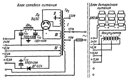
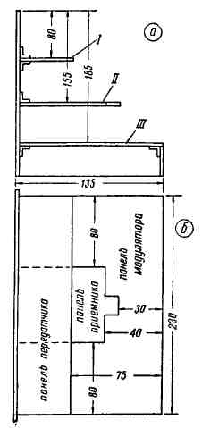
To power the radio station when operating in stationary conditions, a rectifier is used (Fig. 3), consisting of a full-wave rectifier assembled on an L6-kenotron 5TsZS lamp, which serves to power the anode circuits of the radio station lamps, and a half-wave rectifier assembled on a DG-Ts24 type diode, used to power relays, switches of the type of work. Voltages of 6,3 and 12,6 V are taken from the IV winding of the power transformer Tr2. The battery pack combines a filament battery and anode galvanic batteries. Power supplies with the help of connecting cables equipped with chips (for which socles from burned-out lamps can be used) are connected to a contact panel mounted on the radio station case. Construction and details The radio station is enclosed in a wooden box measuring 250x230x150 mm. The installation of the RF components of the transmitter and receiver is made in the form of separate blocks, further combined with an amplifier-modulator on a common basis (Fig. 4).
The location of parts on the transmitter panel is shown in fig. 2, the receiver - in fig. 5. On the front panel of the radio station there are knobs for setting the receiver, volume control, feedback, a switch for the type of work, a rectifier switch, sockets for turning on the receiving and transmitting antennas, telephones and a microphone.
The HF transmitter units were mounted on a getinax panel 2-3 mm thick and 230x60 mm in size. Lamps L1 and L2 are mounted in such a way that one of them is above the contour line, and the other is below it. This is necessary in order to do without long connecting conductors when connecting the anode and grids of these lamps to the line. All dimensions of the line conductors are shown in fig. 2. Antenna connection loop (L3) is made of silver-plated copper wire with a diameter of 2-3 mm. It is soldered to the transmitter antenna sockets and is located at a height of 11 mm above the contour line. High-frequency chokes Dr1-Dr12 frameless winding. They contain 9 turns of wire MG 0,8, the inner diameter of the winding is 5 mm, the length of the winding is 16 mm. In the absence of special small-sized springy lamp sockets, sockets from contact connectors of the ShR type can also be used. The metal base of the L2 lamp is fixed in the hole of the getinax panel using BF-2 glue. Lamp L1 is fixed above the line with a metal square. The installation and location of all parts of the RF generator is strictly symmetrical. For installation, a copper wire with a diameter of 1-1,5 mm is used. RF chokes Dr7 and Dr8 are soldered together with chokes Dr10 and DR11 and resistance R1 to a common ground bus. Decoupling circuit capacitors C1, C2 and C3 are ceramic, it is best to use the KDK-1 type. When installing, you should strive to ensure that the connecting conductors are as short as possible, the entire installation must be rigid and soldering reliable. The HF receiver assembly is mounted on a panel with dimensions of 107x80 mm from sheet getinax or organic glass 3-4 mm thick. The contour line of the receiver is made of copper (or brass) tubes with a diameter of 5 mm. The line tubes are fixed with two 3-4 mm thick organic glass strips. The short-circuit jumper is made of two springy brass strips 0,5 mm thick, fastened with rivets, in the center of which a rod with a handle made of insulating material is strengthened. With the help of it, the receiver is subsequently rebuilt by moving the short-circuit jumper along a segment of the contour line. Antenna communication loop L5 has the same design as L3. The panel for the L3 lamp should be ceramic. Trimmer capacitor C5-ceramic, type K.PK-1, C6 and C7-ceramic type KDK-1 (or mica). The LF amplifier - modulator is mounted on a plate made of sheet aluminum or steel 1-1,5 mm thick with dimensions of 230x135 mm. Dr13 is wound on a core of Sh-15 plates, the thickness of the set is 12 mm. It contains 2500 turns of PEL-0,2 wire. As this inductor, the primary winding of the output transformer, designed for a 6PZS lamp, can also be used. Microphone transformer Tp1 is made on a core of Sh-12 plates, the thickness of the set is 15 mm. Winding I contains 400 turns of wire PEL-0,25, winding II-1600 turns of wire PEL-0,1. Microphone carbon, any type. When using an MB-type capsule, a voltage of 1,5 V is sufficient for normal power supply of the microphone circuit. An element of type 1,5 STMTs-6 or FBS-025 is mounted on the modulator chassis. The transition from reception to transmission is carried out using two electromagnetic relays P1 and P2. As them, small-sized relays of the VSM-1 or RSM-3 type, or any other suitable (for example, telephone) relays, can be successfully used. When installing them, you should only take into account that they are installed at a sufficient distance from each other. Circuits suitable for the contact groups of these relays are shielded. This is necessary to prevent the possibility of parasitic excitation of the modulator. Instead of relays P1 and P2, a conventional two-way two-position switch can be used to switch from transmit to receive. The switch boards must be spaced apart and installed accordingly - one near the L4 lamp, the second near the L5 lamp. All circuits are shielded and located in such a way that the possibility of interconnection between them is minimal. However, despite some additional power consumption, the use of a relay for switching an amplifier-modulator is more desirable, since in this case its setup is greatly simplified. The power transformer Tr2 for the power supply is made on a core of Sh-30 plates, the thickness of the set is 35 mm. The network winding I contains 1135 turns with taps from 550 and 635 turns: 635 turns of this winding are wound with PEL-0,69 wire, the rest with PEL-0,5 wire. Winding II contains 750+750 turns of PEL-0,25. Winding III has 25 turns of PEL-1,2 wire. Winding IV contains 32 turns of wire PEL 1,5 + 32 turns of wire PEL-0,69. Choke Dr14 is made on a core of Sh-19 plates, the thickness of the set is 20 mm. Its winding contains 2500 turns of PEL-0,25 wire. Establishment Setting up a radio station should start with the transmitter. After making sure that the filament circuit of the RF generator is in good condition, we turn on the anode voltage. It is recommended to establish the transmitter at a reduced (up to 150-200 V) anode voltage. For the time of establishment, it is desirable to include a DC milliammeter with a scale of up to 1-2 mA in the power supply circuit of the anodes of lamps L75-L100. If the generator is installed correctly, it will usually start working immediately when it is first turned on. In order to verify the normal operation of the generator, a neon light bulb (for example, type MH-3) is brought to the ends of the line L1-L2. By its glow, you can verify the presence of high-frequency oscillations in the generator circuit. An incandescent light bulb (2,5Vx0,15 a) can also be used for testing. Holding the glass bulb with your fingers, touch the end of the bulb base to the central point of the tube L1, gradually move the bulb along the tube towards one of its ends. The glow of the light bulb, increasing as it approaches the end of the line, will indicate the presence of high-frequency oscillations in the generator loop line. At the same time, observing the readings of the anode milliammeter, a gradual increase in the anode current is noted at the same time. To determine the operating frequency of the generator, it is best to use a two-wire measuring line, the method of working with which has been repeatedly described in radio engineering literature. When adjusting the range of the transmitter, the following factors that affect the frequency of the generator should be taken into account: the length of the line tubes (the shorter the tubes, the higher the frequency), the distance between the line tubes (the greater the distance, the higher the frequency). A change in the distance between the L1-L2 contour line and the communication loop with the antenna, as well as a change in the magnitude of the load at the transmitter output also causes a change in the generator frequency. The transmitter range can also be adjusted using a simple wavemeter, which must first be calibrated using a standard signal generator (for example, GSS-12 type) or a two-wire line and an auxiliary RF generator. Further, with the help of such a wavemeter or field indicator, by changing the distance between the turns of the RF chokes (with the help of tweezers), they achieve maximum output at the transmitter output. After that, the operating voltage (250-300 V) is applied to the generator and, replacing the resistance R1 with a variable resistance of the order of 10 kΩ, focusing on the maximum readings of the field indicator, the most advantageous operating mode of the generator is set. The anode current in this case should not exceed 111 -130 mA. Adjustment of the receiver is reduced mainly to obtaining the most advantageous mode of operation of the superregenerative detector. With proper installation and serviceability of all parts of this cascade, super-regeneration should smoothly appear and stop when the variable resistance engine R4 rotates. The most favorable mode of the super-regenerator, in which its sensitivity will be the greatest, is set using the tuning capacitor C5. When its rotor is rotated with a non-metallic screwdriver, the characteristic noise that accompanies the operation of the superregenerative detector undergoes the following changes: in the position of the maximum capacitance of capacitor C5, it is accompanied by a whistle, then the whistle disappears, then the hiss noticeably increases. At this point, the sensitivity of the superregenerator will be greatest. With a further decrease in the capacitance of the capacitor C5, super-regeneration breaks down. The adjustment of the operating range of the receiver is carried out in the same way as that of the transmitter using a two-wire line or a resonant wavemeter. Its frequency, in addition to the listed factors affecting the frequency of the transmitter, will also be affected by a change in the capacitance of the capacitor C5. The distance between the contour line and the communication loop with the antenna (L5) should be selected very carefully, since with a weak connection, the real sensitivity of the receiver decreases, and with an excessively strong connection, super-regeneration can be disrupted. Authors: V. Lomanovich (UA3DH), D. Penkin (UA3HP); Publication: N. Bolshakov, rf.atnn.ru
A New Way to Control and Manipulate Optical Signals
05.05.2024 Primium Seneca keyboard
05.05.2024 The world's tallest astronomical observatory opened
04.05.2024
▪ To decipher the human genome ▪ Samsung 20nm mobile DRAM chips
▪ site section Lighting. Article selection ▪ Article Unwritten Law. Popular expression ▪ article Why are newspapers with sensational news called tabloids? Detailed answer ▪ article Untying weaving knot. Travel Tips ▪ article Optical telephone. Encyclopedia of radio electronics and electrical engineering
Home page | Library | Articles | Website map | Site Reviews
www.diagram.com.ua |

 Leave your comment on this article: