|
|
ENCYCLOPEDIA OF RADIO ELECTRONICS AND ELECTRICAL ENGINEERING Portable radio station for 430...440 MHz. Encyclopedia of radio electronics and electrical engineering
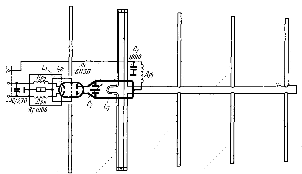
Encyclopedia of radio electronics and electrical engineering / Civil radio communications The article describes a simple and affordable radio station operating in the 430-440 MHz band. Despite its simplicity, in "Field Day" in 1962 it showed good results with a communication range of 40-60 km. After the "Field Day", during a special check, the signals of the transmitter installed on the plain were detected by a communication receiver placed in a car at a distance of up to 200 km. To minimize high frequency losses, the generator is mounted together with a transmitting antenna on a mast (Fig. 1). The transmitter modulator and receiver are located below, on the operator's table. The receiving antenna is 2,1 m below the transmitter antenna. The total height of the mast is about 10 m.
microwave generator. The output power of the generator is approximately 1,8 V / p. The generator is assembled according to the scheme with self-excitation. The simplicity of the circuit allows the use of non-deficient parts and minimizes the establishment of the transmitter, but it also has disadvantages, such as the possibility of spurious frequency modulation. The setting consists in choosing the optimal connection with the antenna (by the glow of a flashlight bulb included in the vibrator circuit) and determining the generation frequency using a measuring line.
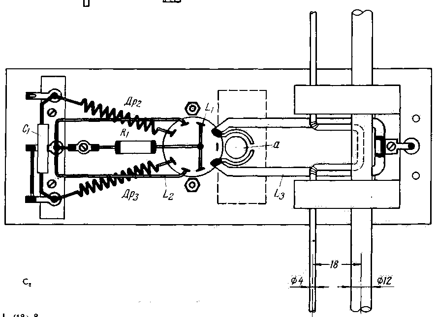
The generator is mounted on an aluminum panel measuring 140x52x2 mm. Of great importance is the quality of the oscillatory circuit in the anode circuit. It is desirable to make a loop (inductance) of this circuit from a silver-plated wire (tube) with a diameter of 3-5 mm. The approximate dimensions of the hinge are 18x52 mm. The rotor of the capacitor C1 is made of two brass plates measuring 12x23 mm. The rotor plates are soldered to the "hot" ends of the anode circuit. The stator is a metal cylinder a 12 mm high and 8 mm in diameter, which is attached to the end of a 3 mm bolt. By screwing in or unscrewing the bolt, you can change the distance between the capacitor plates and so change the generation frequency. The nut must be insulated from the chassis. A brass clamp is attached to the "cold" end of the L3C2 anode circuit, which in turn attaches the anode circuit to the organic glass insulator. A high-frequency choke is soldered to this clamp, which is wound with a 0,6-0,8 PE wire, the winding diameter is 4-5 mm, the number of turns is 10-12 with a winding length of 25-30 mm. Filter capacitor C3 type KSO is located on the back side of the chassis.
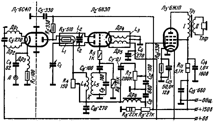
Between the pins of the grids of the 6N3P lamp, there is an L1 loop, 8x18 mm in size, made of 1 mm silver-plated wire and placed vertically with respect to the chassis. The cathode loop L2, made of the same material as L1, has dimensions of 18x45 mm. The midpoint of the cathode loop is grounded. RF inductors in the filament circuits (PE wire 0,8, winding diameter 5 mm) are connected between the generator lamp socket and a special support panel. The antenna vibrator is inductively coupled by means of a 50 mm long coupling loop to the anode circuit and rests on organic glass insulators. The distance between the antenna elements is 138 mm, the length of the reflector is 340 mm, the vibrator is 325 mm, the I director is 310 mm, the II director is 305 mm. III director 300 mm. Tube diameter 12 mm. The mast on which the antenna elements are located has a diameter of 20 mm and must be electrically connected to the chassis. The anode circuits of the generator consume a current of 40 mA at a voltage of 180-210 V. The frequency stability of the transmitter, with careful manufacture, is sufficient for communications lasting no more than 10 minutes. The modulator is powered by a carbon microphone. The output power of the modulator is also sufficient to work with a more powerful generator. The core of the Tp1 transformer is assembled from Sh-12 plates, the thickness of the set is 12 mm. Winding I contains 600 turns of PEL wire 0,08, winding II-9000 turns of the same wire. The transformer core Tr2 is the same as that of Tp1. Winding I has 2000 turns, and winding II has 2x300 turns of PEL 0,11 wire. The windings of the Tp3 transformer are wound on a core made of Sh-16 plates, the thickness of the set is 32 mm. The windings contain: I-2x800 turns, winding II-500 turns of PEL wire 0,18. Receiver has a high-frequency amplification stage, a super-regenerative detector and a low-frequency amplification stage. The RF amplifier on a 6S4P (L1) lamp is made according to a grounded grid scheme. 6S4P can be replaced by 6N3P or 6N15P, while both triodes are connected in parallel. A half-wave loop segment of the line is included in the anode circuit of the RF amplifier. The line is tuned to the middle frequency of the range with a tuning capacitor C2, made of brass plates with a diameter of 12 mm. The superregenerative detector is inductively coupled to the RF amplifier and is similar in design to the generator described above. As a quenching generator circuit, an IF circuit is used, to which a communication winding containing 30 turns of PELSHO 0,16 wire is added. The output transformer Tp1 is assembled on a core of Sh-12 plates, the thickness of the set is 12 mm. Winding I contains 9000 turns of PEL 0,1 wire, and winding II contains 600 turns of the same wire. The receiver antenna has 13 elements with a total length of the mounting mast of 2,45 m. The antenna data are summarized in the table.
Note. All other directors made of copper wire with a diameter of 2 mm have a length of 305 mm and a distance between the elements of 272 mm, the feeder is made of RK-I cable and is consistent with a half-wave U - knee. The anode-screen circuits are powered by a converter (Fig. 4), which is connected to a 12 V battery with a capacity of 60-100 a/h. The heating circuits are powered by a 6 V battery. The current consumed from the incandescent battery is 1,7 A and from the anode battery 1,5 A. P4 transistors can be used in the converter. The windings of the transformer Tp1 have: winding I-2x45 turns of wire PEV-2 0,64, winding II-2x23 turns of wire PEV-2 0,31, high voltage winding III-800 turns of wire PEV-2 0,18. The transformer is assembled on a Sh-12 permalloy core, with a set thickness of 16 mm. Windings l and ll are wound together; then you should cut the middle of the wire and connect the end of one of the resulting windings to the beginning of the other, this connection is the midpoint of this winding. To prevent higher harmonics from creeping in front of the rectifier bridge, a trap filter is included from the resistances R4 and R5 and capacitors C3C4. Filter capacitors of the KSO type must be designed for an operating voltage of at least 500 A. The converter operates at a frequency of about 800 Hz and has an efficiency of about 75%. To reduce losses at high frequencies, the microwave generator is mounted together with the transmitting antenna on the mast. The generator is mounted on an aluminum panel measuring 140x52 mm. The loop of the anode circuit L3 is made of a silver-plated tube with a diameter of 3-5 mm. Loop dimensions 18x52 mm. The rotor of the capacitor C2 is made of two brass plates, the stator is a metal cylinder, its height is 12 mm, its diameter is 15 mm. The "cold" end of the anode circuit is attached to the organic glass insulator with a brass clamp. A loop L1 (18x8 mm) of silver-plated wire 1 mm in diameter is connected between the grid leads. Author: I. Ottoson (UR2RDB), Tallinn; Publication: N. Bolshakov, rf.atnn.ru
A New Way to Control and Manipulate Optical Signals
05.05.2024 Primium Seneca keyboard
05.05.2024 The world's tallest astronomical observatory opened
04.05.2024
▪ Smart car video processor GEO GW5 ▪ The value of the Casimir torque is measured ▪ Device against decompression sickness
▪ section of the site Experiments in chemistry. Article selection ▪ article Ostrovsky Alexander Nikolaevich. Famous aphorisms ▪ article Does techno have anything to do with rock music? Detailed answer ▪ article Dust and gas contamination of industrial premises ▪ article Piezoelectric filters on SAW. Encyclopedia of radio electronics and electrical engineering
Home page | Library | Articles | Website map | Site Reviews www.diagram.com.ua |


 Arabic
 Bengali
 Chinese
 English
 French
 German
 Hebrew
 Hindi
Hindi Italian
 Japanese
 Korean
 Malay
Malay Polish
 Portuguese
 Spanish
 Turkish
 Ukrainian
 Vietnamese


 Leave your comment on this article: