|
|
ENCYCLOPEDIA OF RADIO ELECTRONICS AND ELECTRICAL ENGINEERING Powerful transistor in avalanche mode. Encyclopedia of radio electronics and electrical engineering
Encyclopedia of radio electronics and electrical engineering / Radio amateur designer The use of transistors in the avalanche mode makes it possible to simplify some circuits, obtain high output voltages, high speed, which are not achieved when transistors operate in normal modes. There is. however, there are a number of reasons that make it difficult to widely use the avalanche mode of operation of transistors. First of all, we should mention the significant spread of the avalanche parameters of transistors and, as a result, the insufficiently high reproducibility of the characteristics of devices based on transistors operating in such a mode. In addition, there is always a great danger of a breakdown of the transistor in the process of setting up devices. However, despite the formal reasons (the absence in the technical specifications of an indication of the possibility of operating in the avalanche breakdown mode), the use of conventional transistors in the avalanche breakdown mode is fully justified in electronic devices manufactured in single copies, when conducting experiments, in amateur radio designs, etc. Good results can be obtained when using a powerful silicon transistor P701A in the avalanche mode. On fig. 1 shows a diagram of a sawtooth voltage generator operating in a self-oscillating mode.
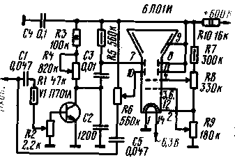
The generator produces sawtooth pulses with a frequency of 20 ... 250 Hz, 200 ... 2500 Hz and 2000 ... 25 Hz (position 000, 1, 2 of switch S3) and an amplitude of 1 V. At frequencies above 120 kHz, the voltage amplitude decreases to 20 V. The linearity of the sawtooth voltage is quite high, its deterioration occurs only at the lowest frequencies of the first subrange. The generator is easily synchronized by an external signal with a frequency of up to hundreds of kilohertz and a voltage of several volts. The input impedance for the sync signal is about 100 kOhm. With a supply voltage of 90 V, the generator consumes from 600 to 0,5 mA (a larger value corresponds to a higher frequency of each subrange). When the generator is connected to a power source, the voltage at the collector of the transistor and capacitor C2. equal to zero at the initial moment (the transistor is locked), begins to increase exponentially at a rate determined by the time constant of the R5R6C2 circuit. When a certain voltage is reached on the collector of the transistor, it is unlocked, the capacitor C2 is discharged through it. the voltage across the capacitor drops sharply to zero, after which the process repeats. By applying an alternating voltage to the base circuit, you can control the moment the transistor opens, which ensures its synchronization. Establishing the generator is reduced to the selection of such a position of the engine of the tuning potentiometer R4, in which stable oscillations will be maintained at any position of the resistor R6 and switch SI. If this does not work, then increase the supply voltage and. maybe replace the transistor. During prolonged operation of the generator in the high-frequency sections of the subranges (resistor R6 in the position of minimum resistance), the transistor may slightly heat up; in order to avoid this, it is advisable to mount the transistor on a radiator. The generator can operate without any changes in the circuit at a supply voltage of 300 to 800 ... 1000 V. The amplitude of the sawtooth voltage of the generator changes slightly, while the frequency range. blocked by the generator, with a decrease in the supply voltage, it will mix towards low (up to 5 ... 10 Hz), and with an increase - towards higher frequencies (up to 30 kHz). The above parameters of the generator were obtained with a supply voltage of 600 V. Having such a sawtooth voltage generator, it is not difficult to assemble a simple oscilloscope, for example, with a 6L01I tube. A diagram of such an "oscilloscope-attachment" is shown in fig. 2. With it, you can observe the waveform with an amplitude of 5 V in various circuits of the TV. The supply voltage to the oscilloscope is supplied from the voltage boost circuit of the TV (500-800 V).
The sweep range is used only one - 2000 ... 20 000 Hz. In this case, a bias voltage sufficient for the normal operation of the generator is created due to the flow of current through the resistor R2. The sawtooth voltage from the collector of the transistor through the coupling capacitor C3 is supplied to the horizontal deflecting plates of the tube. The voltage under investigation is supplied to the vertical plates through a separating capacitor C5 and a potentiometer R6, which regulates the size of the vertical image. The same voltage is supplied through the decoupling capacitor C1 and the resistor R1 to the potentiometer R2, which serves as a synchronization regulator. Potentiometers R9 and R8 are used to adjust the brightness and focus, respectively. Resistor R10 and capacitor C4 form a filter that prevents horizontal frequency interference from penetrating into the power supply circuit. Capacitors used in the oscilloscope must be designed for an operating voltage of at least 750 V. Potentiometer R4 - for a power of 2 watts. To center the beam of the tube, a magnetized piece of iron wire is used, or a screw with a diameter of 3 ... 5 mm, or a piece of a ferrite corrective core from the deflecting TV systems. The magnet is placed directly on the flask of the tube and fixed in the selected position with adhesive tape. It is convenient to connect the oscilloscope-set-top box to the TV using conductors with alligator clips. The signal under test must be applied to the input using a shielded cable. Although there is no signal amplifier in the design, interference from the TV scanner unit may adversely affect the tube. For this reason, during operation, the oscilloscope must be located at a sufficient distance from the TV scanner. If desired, a metal shielding casing can be made for the oscilloscope. The oscilloscope is set up in the following order. The potentiometer slider R6 is moved to the upper position according to the diagram, and terminal 7 of the deflecting plate of the tube is connected to terminal 9 (without soldering from C5 and R6}. The resistor R3 is disconnected from the 6t positive wire. By applying the supply voltage to the oscilloscope, check the operation of the regulators R9 (brightness) and R8 (focus) and, having received a luminous spot on the screen, mix it with a magnetic core to the central part of the screen.Next, pin 7 is disconnected from pin 9 and the connection of the resistor R3 with the positive wire is restored.After that, the supply voltage is again applied to the oscilloscope.On the screen tube, with the appropriate position of the brightness control, a horizontal line will appear, the length of which should be approximately the same for any position of the frequency control R4. If there is no sweep (instead of a line on the screen, a dot), a bias voltage should be applied to the base of the transistor from the divider, as in Fig. 1, or replace the transistor. In the oscilloscope, instead of the 6L01I tube, you can use almost any oscilloscope tube with a voltage on the second anode up to 1000 V. If necessary, a phase voltage can be obtained from an avalanche transistor generator. On fig. 3 shows a diagram of such a generator. In principle, it does not differ from those shown in Fig. 1 and 2. Paraphase sawtooth voltage is obtained by dividing the resistance of the charging circuit (resistors R4 and R5). The parameters of the generators assembled according to the schemes of fig. 1 and 3 are the same.
Good results are obtained if the P701A transistor operating in the avalanche breakdown mode is used for amplification. On fig. 4 shows an amplifier circuit in which the P417 transistor is used to increase the input resistance. The band of amplified frequencies at the level of 0,7 is 50...20 Hz. The voltage gain measured at 000 kHz is about 4. The input impedance is over 120 kΩ. The highest output voltage reaches 100 Vrms. The amplitude characteristic of the amplifier is linear when the signal voltage at the input changes from 70 to 0 V. At a supply voltage of 0,6 V, the amplifier consumes a current of about 600 mA. It is very convenient to use in conjunction with the sweep generators described above in an oscilloscope.
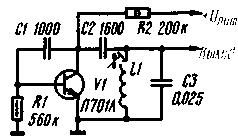
Avalanche mode transistors work best in relaxation oscillator circuits. However, under certain conditions, the avalanche transistor generator can produce sinusoidal oscillations. The generator according to the scheme of fig. 5 generates a sinusoidal voltage with a frequency of about 4 kHz and an amplitude of more than 110 V. With a supply voltage of 600 V, the current consumption is about 2 mA.
RLS-70 row size regulator is used as an inductor. Both the shape and the magnitude of the output voltage of the generator are highly dependent on the capacitance of the capacitor C1. To change the oscillation frequency, it is necessary to select first the capacitance of the capacitor C2, and then C1. Author: A. Piltakyan, Moscow; Publication: N. Bolshakov, rf.atnn.ru
A New Way to Control and Manipulate Optical Signals
05.05.2024 Primium Seneca keyboard
05.05.2024 The world's tallest astronomical observatory opened
04.05.2024
▪ A more effective analogue of a lie detector ▪ Car Wi-Fi will improve road safety ▪ The effectiveness of exercise depends on the time of day
▪ section of the website Experiments in Physics. Selection of articles ▪ article Keynesianism. History and essence of scientific discovery ▪ article Where Does the Wind Come From? Detailed answer ▪ Margarine article. Simple recipes and tips ▪ article Transmitter for sports DF. Encyclopedia of radio electronics and electrical engineering
Home page | Library | Articles | Website map | Site Reviews www.diagram.com.ua |


 Arabic
 Bengali
 Chinese
 English
 French
 German
 Hebrew
 Hindi
Hindi Italian
 Japanese
 Korean
 Malay
Malay Polish
 Portuguese
 Spanish
 Turkish
 Ukrainian
 Vietnamese


 Leave your comment on this article: