
|
|
ENCYCLOPEDIA OF RADIO ELECTRONICS AND ELECTRICAL ENGINEERING TURBO-TEST transmitter. Encyclopedia of radio electronics and electrical engineering
Encyclopedia of radio electronics and electrical engineering / Civil radio communications The transmitter set-top box for the radio receiver "TURBO-TEST" (see "HF Journal", 1993, No. 1, p. 23-27 and No. 2-3, p. 31-35) is designed to operate CW and SSB on amateur HF bands 1,8 ,3,5; 7; 10; 14; 18; 21; 24; 28; 10 MHz. Output power on all the above ranges - at least 75 watts. The transmission path is designed for a load with a resistance of 220 ohms. Food - from the alternating current main 50 V XNUMX Hz. Schematic diagram of the attachment is shown in Fig.1. When SSB is working, the audio signal from the microphone is fed through the level control R1 to the input of the microphone amplifier (IC DA1). The L1C3 low-pass filter attenuates high-frequency interference from its own transmitter to the input of the microphone amplifier and thereby reduces the risk of its self-excitation. From the output of this amplifier, through an additional low-pass filter (L2C8C9), the signal is fed to a ring diode modulator on diodes VD1-VD4. A "non-polar" decoupling capacitor at the output of the microphone amplifier (capacitors C6C7 connected in series) prevents modulator imbalance due to changes in the leakage resistance of the oxide capacitor over time.
Table
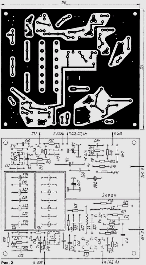
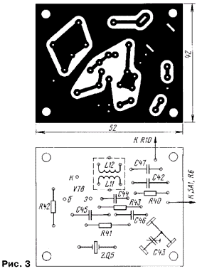
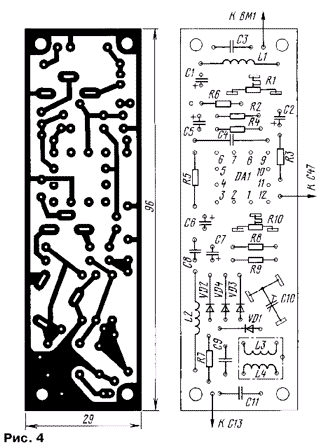
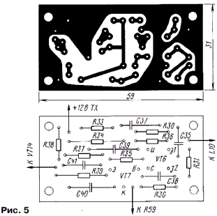
From the reference quartz local oscillator, which is assembled on a VT8 transistor, a high-frequency voltage with a frequency of 9 MHz is applied to the modulator. Trimmer resistor R10 and trimmer capacitor C10 are used to balance the modulator. The generated DSB signal is fed to the first gate of the transistor VT1 of the IF amplifier. A control voltage of 59 ... + 0 V is supplied to the second gate of this transistor from resistor R5 (gain control of the high-frequency cascades of the set-top box). From the circuit L5C15, included in the drain circuit of the transistor VT1, the amplified DSB signal is fed to the main selection filter. The four-crystal quartz filter on the ZQ1-ZQ4 resonators singles out one sideband and suppresses carrier remnants. The signal is amplified by the second IF stage (on transistor VT2) and then fed to the mixer. It is made on transistors VT3 and VT4 according to the so-called "quasi-balanced circuit". The GPA signal (the receiver local oscillator signal is used) is fed through the capacitor C30 to the gate of the transistor VT4. The radio frequency signal is taken from the drains of the VТЗ, VT4 transistors and then amplified by a broadband cascade made on the VT5 transistor connected according to a common base circuit. Its low input impedance provides good mixer stability, the high output impedance combined with the high input impedance of the next stage provides good filtering of spurious signals by the L10C36 single loop. Further, the signal generated at the operating frequency is amplified by a three-stage power amplifier. The first stage is an adjustable field-effect transistor amplifier (VT6), the second is an emitter follower (VT7), the third is a terminal one (VT13, VT14) on two transistors connected in a cascode circuit. The load of the final stage is a step-up transformer T2, from which the signal, through the contacts K2.1 of relay K2, enters the P-loop L14C69-C77. Such a circuit design made it possible to use a tuning capacitor C69C70 of small capacity in the P-loop, obtain a high quality factor of the P-loop (which favorably affects the spectral purity of the output signal) and reduce the criticality of the amplifier to the length of the connecting conductors (increase resistance to self-excitation). From the output of the P-loop, the RF signal is fed through socket XW1 to the antenna. In the receive mode, relay contacts K2 connect the antenna input of the receiver through the P-loop to the XW1 antenna. In the antenna transmission mode, the receiver input is connected to a common wire. An ammeter PA13 is included in the collector circuit of the transistor VT1. According to the minimum of its readings, the P-circuit is tuned to the operating frequency. The set-top box is switched to the telegraph mode with the SA1 toggle switch. In this case, the supply voltage is applied to the telegraph quartz local oscillator, made on a VT9 bipolar transistor, and it is removed from the microphone amplifier and the reference quartz local oscillator. The generator is manipulated along the collector circuit (switch SA2 imitates a telegraph key in the diagram). Operation in CW mode is otherwise similar to the operation of the set-top box in SSB mode. The set-top box power supply includes a T1 power transformer, two rectifiers (VD5-VD8, VD9-VD12) and a voltage regulator (DA2, VD13, VT10-VT12). Unstabilized voltages +40 V and +20 V are used, respectively, to power the output stage of the power amplifier and the windings of relays K1 and K2. Stabilized voltage +12 V - to power the remaining stages of the set-top box. Resistor R55 ("CK" - self-control) regulates the gain of the "TURBO-TEST" receiver in transmission mode, setting the required level of self-listening of its signal when working by telegraph. Through the same resistor, the receiving path is closed in the transmission mode during SSB operation. Resistor R55 is connected to the AGC circuit of the receiver (to the collector of the VT13 transistor of the "TURBO-TEST" receiver). The main part of the parts of the transmitting attachment is installed on five printed circuit boards made of foil fiberglass 1,5 mm thick. Drawings of printed circuit boards and the location of radio components on them are shown in fig. 2-6. On the main board (Fig. 2), the cascades of the IF, FOS, telegraph local oscillator, mixer and silo are mounted. Also on this board, it is possible to install additional four quartz resonators to implement an eight-crystal quartz filter.
Payment in fig. 3 - reference crystal oscillator, board in fig. 4 - microphone amplifier and modulator, board in fig. 5 - the first and second PA stages, the board in fig. 6 - rectifiers and stabilizer.
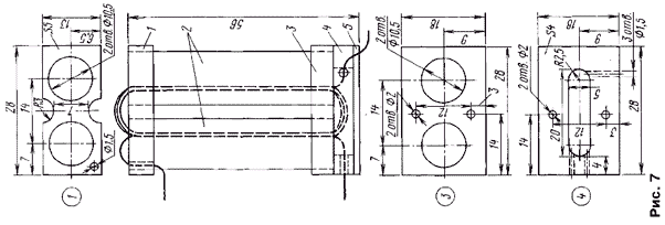
The final stage of the power amplifier is made by a hinged method in a separate compartment, shielded by aluminum partitions. Details of the P-loop are also installed in a separate shielded compartment. The set-top box uses widely used radio components: MLT fixed resistors, SP3-9a, SP3-1b, SP3-4 variables, KM, KT, K50-6, K53-4, KPK-MP capacitors. Capacitor C36 type KVP-100 (KPV-125, KPV-140). Dual block KPE S69S70 - from the Alpinist radio receiver. Switches SA4 - biscuit 11P3N, SA1, SA3 - microtumbler MT-1. Relay K1 type RES22 (passport RF4.500.131), relay K2 type RES54 (passport KhP4.500.011-02) Transistors KP350B can be replaced with KP306, KP303E with KP307, KT603B with KT608, KT660 (with any letter indices), KT306B with KT342B, KT361B with KT363A(B), P216 with P217. The PA1 device is a milliammeter with a total deflection current of at least 500 mA. The winding data of the coils and transformer T2 are given in the table. Inductors L2 (inductance - 200 μH ± 5%), L8 and L9 (30 μH ± 5%), L13 (160 μH ± 5%) - unified DM 0,2. The design of the transformer T2 is shown in fig. 7. Its magnetic core 2 is made up of two halves, each of which is formed by ten ferrite rings of the M600NN brand, size K10x6x5 mm, fastened with a strip of cable paper lubricated with Mars glue. The magnetic circuits can also be made from ferrite tubes of suitable size. From above, they put on the resulting tubes, with the same glue, clip 1, from below - clip 3, after which the windings are wound with MGTF 0,35 mm wire. The primary (included in the collector circuit of the VT13 transistor) winding must contain 2,5, the secondary - 8 turns. Then block 4 is applied to the lower clip, having previously passed the winding leads through the holes drilled in it, and plate 5 to it (it differs from clip 3 in the absence of holes with a diameter of 10,5 mm and a smaller thickness of 1,5 mm). Then these parts are fixed with two M2,5 screws, screwing them to the chassis. Details 1, 3-5 are made of fiberglass.
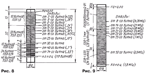
Coils L10, L14 are wound on ceramic frames. Their design and winding data are shown in Fig. 8 and 9 respectively.
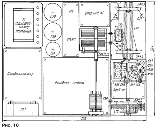
Network transformer T1 - type TS-40-2 (af0.470.025TU) with a primary winding of 220 V and two secondary windings of 18 V. The transmitter attachment is made in a housing with dimensions of 255x204x114 mm made of duralumin. The chassis is made of dural plate 4 mm thick. Chassis basement depth - 22 mm. A top view of the mounting of the attachment is shown in fig. 10.
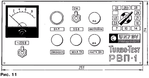
On the front panel (Fig. 11) are pasted strips of paper with printed designations of controls. The front panel is covered with a transparent plexiglass plate 2 mm thick, which protects the inscriptions from damage. Installed on the front panel: device PA1, signaling indicator for turning on the set-top box (not shown in the diagram in Fig. 1), toggle switches SA1, SA3, switch SA4, resistors R59, R55, and also output, through insulating leads, the axes of capacitors C36, C69, C70 . The FU1 fuse, sockets and connectors are installed on the rear panel.
The tincture of the set-top box begins with checking the installation for the absence of short circuits in the power circuits. In the absence of any or after they have been eliminated, turn on the power supply at idle (the set-top box nodes are disabled) and make sure that there are supply voltages of more than +40 V at the positive output of C58, more than +20 V at the positive output of C59 and +12 V at the positive output of C61. The voltage of +12 V is set with a trimming resistor R50. After that, you can connect all stages to the power supply according to the circuit diagram and continue tuning in SSB mode. The normal operation of the microphone amplifier is verified by connecting the headphones to the connection point of the cathodes of the C6C7 capacitors relative to the case and listening to the output low-frequency signal. Next, the reference local oscillator is launched on VT8. By rotating the trimmer of the L11C44 circuit, stable generation of the local oscillator at the frequency of quartz and the maximum amplitude of the RF voltage at the output are achieved. Subsequently, the oscillator frequency is set to the lower slope of the quartz filter characteristics by adjusting the capacitor C43. For control, a high-resistance RF voltmeter, an oscilloscope and a frequency meter are used. Further, with an unbalanced modulator (the engine of the tuning resistor R10 is brought to one of the extreme positions), by rotating the trimmer, the L4C11 circuit is tuned to resonance. Then the L5C15 and L7C25 circuits are tuned to resonance according to the maximum high-frequency voltage at the gate of the VT3 transistor. The crystal filter ZQ1-ZQ4 is adjusted by selecting capacitors C18-C21. Its amplitude-frequency characteristic is taken using a frequency response meter or GSS, applying a measuring signal to the left terminal of the capacitor C13 (it is pre-soldered from other elements). By applying a GPA receiver signal to the second input of the mixer (gate VT4) and adjusting the capacitors C36, C69, C70, they achieve the maximum signal on the antenna equivalent, which is used as a non-inductive resistor 75 Ohm 10 W or an incandescent bulb for a voltage of 28 V and a power of 10 W, connected between the antenna socket XW1 and the chassis. An oscilloscope is connected in parallel with the equivalent. The control is carried out by the current decline, following the readings of the RA1 device. By adjusting the resistor R57, the maximum signal is achieved on the equivalent with a sinusoidal waveform. Further, having previously turned off the microphone, the modulator (VD1-VD4) is balanced with a trimmer resistor R10 and a trimmer capacitor C10 according to the minimum signal on the antenna equivalent. After connecting the microphone, they say a long "a..a..a" in front of it and make sure that there is a single-band signal at the output of the set-top box. The output power is adjusted by resistor R59. Then the SA1 switch puts the prefix in the telegraph mode. With the key pressed (closed contacts of the SA2 switch), by adjusting the capacitor C49, the frequency of the telegraph local oscillator is set to the middle of the passband of the quartz filter. Capacitor C53 sets the output power in CW mode so that it approximately corresponds to the output power in SSB mode. By selecting capacitor C51, the required steepness of the slopes of telegraph parcels is set by the absence of clicks or "hardness" in the CW signal (the signal is controlled by the receiver). Resistor R55 sets an acceptable level of self-control of their own telegraphic messages. Author: V.Rubtsov (UN7BV)
The world's tallest astronomical observatory opened
04.05.2024 Controlling objects using air currents
04.05.2024 Purebred dogs get sick no more often than purebred dogs
03.05.2024
▪ A tomograph is more efficient than a polygraph ▪ Purity of speech affects memory ▪ Apple phones will be able to fall like cats ▪ Plextor M8V Plus Solid State Drives
▪ section of the site Microcontrollers. Article selection ▪ Article Investments. Lecture notes ▪ article How to determine the age of a tree? Detailed answer ▪ dog rose article. Legends, cultivation, methods of application ▪ article Three-channel multimedia UMZCH. Encyclopedia of radio electronics and electrical engineering ▪ article Glass piercing. Focus secret
Home page | Library | Articles | Website map | Site Reviews www.diagram.com.ua |


 Arabic
 Bengali
 Chinese
 English
 French
 German
 Hebrew
 Hindi
Hindi Italian
 Japanese
 Korean
 Malay
Malay Polish
 Portuguese
 Spanish
 Turkish
 Ukrainian
 Vietnamese



 Leave your comment on this article: