|
|


 Arabic
 Bengali
 Chinese
 English
 French
 German
 Hebrew
 Hindi
Hindi Italian
 Japanese
 Korean
 Malay
Malay Polish
 Portuguese
 Spanish
 Turkish
 Ukrainian
 Vietnamese
|
ENCYCLOPEDIA OF RADIO ELECTRONICS AND ELECTRICAL ENGINEERING Miniature FM radio station in the range of 2 meters. Encyclopedia of radio electronics and electrical engineering
Encyclopedia of radio electronics and electrical engineering / Civil radio communications The radio station proposed in this article has a small weight and dimensions. It is easy to use, because it has a minimum of controls. The radio station is made on SMD components, is easily repeatable, inexpensive to manufacture and easy to assemble, has good parameters for receiving and transmitting. To simplify the design of the frequency indicator, the station does not have, but the searchless operation mode is used (three operating frequencies pre-recorded in the radio station's memory). At the same time, there is a scanning mode over the entire authorized FM section, which allows you to find a correspondent, fix on his frequency and make contacts.
In general, the device is a full-fledged radio station, in many respects not inferior to industrial devices. It has the following specifications:
The scheme of the radio station is shown in fig. 2. The receiving path is made according to the double frequency conversion scheme and consists of the ULF VT1, the first mixer on the VT2 transistor, the intermediate amplifying stage VT3, the DA1 functional microcircuit (MC3361 from Motorola) and the ULF on the DA2 microcircuit.
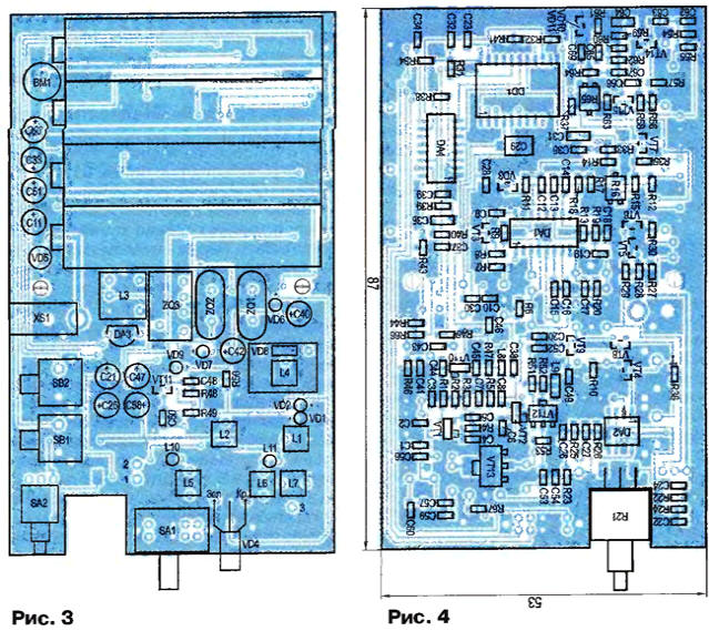
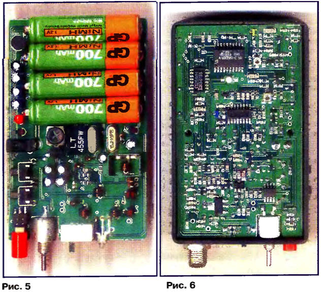
In the receive mode, the signal from the antenna through the XW1 connector, the L7 coil, the capacitor C1 is fed to the input circuit L1C2, and then to the first gate VT1. Further, the amplified signal is selected by the oscillatory circuit L2C6 and is fed to the first gate of the transistor of the first mixer VT2. The signal of the 8st local oscillator, taken from the voltage controlled generator (VCO) on \/T1, which is common to the receiver and transmitter, is fed to the second gate through the capacitor C10. The VCO is controlled by a synthesizer made on DD1 and DA1 microcircuits. The mixer on VT2 operates with zero initial offset on the gates. This made it possible to obtain low mixer noise, good linearity and a high conversion factor. The signal of the first IF with a frequency of 10695 kHz is selected on the resistor R6 and through the quartz filter ZQ2 enters the amplifying stage on the transistor VT3. The amplified signal is fed to the input of the second mixer (pin 16 of the DA1 chip). The signal from the crystal oscillator of the synthesizer driver with a frequency of 1 kHz is fed to the other input of this mixer (pin 10) through the capacitive divider C30C10240. As a result of mixing the two signals, a 455 kHz second IF difference signal is generated. Then it goes through the ceramic FSS ZQ3 to the IF and the detector, which are part of the DA1 chip. The inclusion of the microcircuit is typical, except that the noise amplifier filter values are slightly optimized in order to make it work more clearly and protect against false noise suppressor responses with large deviations of the received signal. The low-frequency signal is removed from the filter R19C18 and fed through the volume control R21 to the ULF DA2. In the absence of a received signal, the ULF is closed by a high logic level signal supplied from pin 19 of the DD1 processor to pin 1 of DA2 (control). In the presence of a radio station signal, a positive voltage appears at the trigger output as part of DA1, which opens the VT10 key through R4, thereby setting a low logic level at pin 1 of DA2, bringing the ULF into operating mode. In parallel with VT4, a button for forced shutdown of the SHP SB2 is installed. The response threshold of the SHP is set by resistor R16. In general, the operation algorithm is as follows: when the power switch SA2 is turned on, the DD1 processor is set to the operating mode. At pin 13 of the microcircuit, there is a logical 0, which, through the resistor R41, opens the VT9 key in the power supply circuit of the receiver. Power from this key through the R42VD7 circuit is supplied to the VCO. If at the same time there is no working station (the noise suppressor is closed), then after 4 s the processor switches to economy mode and turns on the power in "portions" of 0,3 s every 0,9 s. Power supply is indicated by a flashing green LED VD4.1. If there is a station and the squelch has worked, then the VT4 key sets logical 0 at pin 19 of the processor and it goes into operating mode. The ULF is also turned on. The processor will be in working condition as long as there is activity in the reception-transmission or working stations, i.e. opening the squelch. After 4 seconds of the absence of a received signal and transmission, the processor again puts the station into economy mode. To turn on the scan mode, when the radio is off, press the SB1 transmission button and turn on the power. Release SB1 1 s after power is applied. Scanning indicates frequent flashing of the VD4 LED. When a running station is detected, scanning pauses for 3 seconds, then continues on. You need to stop scanning by briefly pressing the transmission. The station will stay on the fixed frequency until the power is turned off. After the power is turned on again, in accordance with the position of the switch SA1, the frequency recorded during the manufacture of the radio station in the memory is set. The transmission is switched on by pressing the SB1 button. This switches the processor mode at pin 16 DD1, also opens the VT36 key through R8 and blocks the power supply to the receiver. Control through R37 opens the VT7 key, which supplies power to the preliminary stages of the transmitter and the microphone amplifier. The glow of the red LED VD4.2 indicates the transmission mode. The microphone amplifier is assembled according to a scheme with a direct connection between the cascades on transistors VT14 and VT15. In the amplifier, frequency correction is carried out with a frequency response rise of about 6 dB per octave to a frequency of 3 kHz and a further blockage of the frequency response. The amplifier has a relatively low-impedance output and amplifies the low-frequency signal up to an amplitude of 1,5 V, equal to its supply voltage. This made it possible to use a simple diode limiter and provide a small degree of compression without causing noticeable distortion. The amplifier is not sensitive to powerful RF fields and provides a good sound for transmission. Frequency modulation is carried out by applying a low-frequency signal through R65 to the VD8 varicap, which rebuilds the VCO with control from the synthesizer and serves to switch its natural frequency when switching from reception to transmission. In receive mode, a positive bias voltage is applied to the varicap through the R43C40R44 circuit. The VCO is made on a VT10 field-effect transistor according to a capacitive three-point circuit. The use of a field-effect transistor in the generator made it possible to obtain good intrinsic stability and a clean oscillation spectrum. The generator also agrees well with the subsequent stage and, in the loaded state, develops an amplitude in the transmission mode of about 0,8 V, which, on the whole, made it possible to simplify the transmitter. The amplifying part of the transmitter contains three stages on transistors VT11, VT12, VT13, respectively. The cascades on transistors VT12 and VT13 are initially locked, so the power to them is not switched and is constantly supplied. VT12 operates in class B mode with a small bias removed from the VD9 diode, and VT13 operates in class C mode without bias and has a high efficiency. The amplified signal is fed to the antenna through the matching circuits and the XW1 connector. All circuits of the radio station, with the exception of the ULF and the output stage of the transmitter, are powered by a DA3 stabilizer with a stabilization voltage of 3,3 V. As a result, all radio station parameters are saved up to the discharge. To control the discharge, a threshold device on transistors VT5 and VT6 and an LED VD5 are used. The station is assembled on a single printed circuit board made of double-sided foil fiberglass with dimensions of 87x53 mm, made according to modern technology, with metallization of holes and a protective mask sized along the inner perimeter of the case, which gives it additional strength. The tracing of the sides of the board is shown in fig. 3 and 4. The board does not have special fasteners, it is simply inserted into the case and pressed against the back cover, which is fastened with two screws. Pre-solder only the speaker and the wire from the antenna connector.
When assembling, mainly SMD elements were used: resistors and capacitors of inch size 0805 (but they can be replaced with elements of inch size 1206). Trimmer resistors and capacitors, also used for surface mounting. All oxide capacitors are 6,3 V. The coils of the circuits are frameless (except for L3), wound on a mandrel 3 mm with PEL 0,5 wire. Coils L1, L2, L5, L6 contain 4 turns, L4 - 5 turns, L7 - 3 turns. Coil L3, with an inductance of 680 μH, is used either standard at 455 kHz in an 8 mm screen, or wound on a suitable fitting with a ferrite core and a tuning cup and contains 150 turns of PEL 0,08 wire. Inductors L8, L9 - chip inductances of 0,033 and 0,47 μH, respectively, L10 - ordinary with pin leads with an inductance of 1 μH. The L11 inductor has 5 turns of PEL 0,5 wire wound on a 2,2 mm mandrel and is located vertically on the board. Diodes VD1, VD2 VD6, VD7, VD9 - KD521, KD522. Diode VD3 - a diode assembly of the BAV70 series with combined cathodes (diodes are connected in parallel in the radio station), and VD10, VD11 - BAV99, containing two diodes connected in series (their midpoint is connected to capacitor C69 and resistors R64, R65). LED VD5 - AL102A, VD4 - two-color (two diodes in one housing). Transistor VT3 - domestic SMD KT368A9. Domestic SMD transistors PNP - KT3129A9 and NPN - KT3130A9 are also used in LF and switching circuits. Chip DA4 - KF1015PL4. Microphone - any electret, with a diameter of 6 mm, dynamic head BA1 - any, with a diameter of 40 mm, winding resistance 8 ohms.
To shield the VCO contour, a self-made rectangular screen measuring 8x11 mm is used, made from a strip of tinplate 7 mm wide. To solder it on the board there is a circuit without a mask. After tuning from above, it is closed with a U-shaped plate of the same material and sealed at two or three points. Microcontroller firmware and PCB trace files Subject to all the indicated ratings, the circuit works almost immediately and requires only minimal adjustment. Before starting the tuning, it is recommended to de-energize the output stage of the transmitter. To do this, you need to unsolder one output of the inductor L11. Turn off the squelch by turning the resistor R16 or temporarily installing a jumper instead of SB2. The first thing to do is tune the VCO. To do this, you need to measure the voltage at pin 15 of the DA4 microcircuit and, with the gear pressed, pushing the turns of the L4 coil, set the voltage to about 1 ... 1,3 V. When the transmission is released in the receive mode, the voltage should remain approximately the same. If it is very different, then the resistor R46 should be selected so that the difference in the receive-transmit modes is minimal. After that, the L4 coil should be filled with paraffin.
Next, you need to connect a frequency meter to the antenna output and, when transmitting with a trimmer capacitor C29, set the frequency corresponding to the switch position (the frequencies are determined by the DD1 firmware program). You can set the deviation with the R65 resistor using instruments or using a control station for the loudest, undistorted sound when talking near the microphone. Then apply from the GSS to the input of the receiver a radio signal of the appropriate frequency with a deviation of 3 ... 4 kHz and adjust the receiver with the L3 coil for the loudest and most undistorted signal. To complete the adjustment of the receiver, set the maximum sensitivity by slightly pushing the turns of the coils L1 and L2. After completing all the previous work, solder the L11 inductor in place, connect a 1 Ohm load equivalent to the XW50 connector and measure the transmission voltage on it. The maximum power output is set by slightly pushing the turns of the coils L5 and L6. The load voltage must be at least 11...12 V, which corresponds to an output power of 2,4...2,8 W. Then resistor R16 set the threshold of the SR. Without a signal, the station should be completely silent and turn on confidently even with a weak signal with noise. The radio station antenna is resonant with an electrical wire length of 0,75 wavelengths. An antenna is made on the basis of a segment of a 75-ohm RCI television cable, with an outer diameter of 7 mm, a length of 10 cm. It is necessary to remove the outer sheath from it, remove the braid and the central conductor. It comes off easily with no effort. Then the shell is put back on. At a distance of about 10 mm from the edge, using the "native" central conductor, the insulation is punctured and the end of the wire is brought out in the center, and the other is bitten off and bent onto the insulation for further soldering the spiral wire to it. For the spiral, a double-folded MC wire in PTFE insulation, with an outer diameter of 0,5 mm, is used. Winding is performed turn to turn. The length of the conductor folded in half is 106 mm. But it is better to take a deliberately large length, about 115 mm, and then fine-tune by shortening. One end of the conductor is soldered to the central conductor and gently melted into the insulation. After that, winding is performed and the wire is fixed at the end. A connector is installed from the side of the central conductor. Then, a heat-shrinkable tube is put on the entire structure and fixed by heating over a light flame. Tune the antenna using a frequency response meter or by a field strength indicator using the radio station itself. In this case, it is better to de-energize the transmitter output stage. The output RF power is about 30 mW, which is quite enough to operate even the simplest field indicator. Tuning with frequency response devices is easier to perform. Connect the input of the device to the output of the final stage (according to the diagram, this is point 3) and connect the antenna to this point. Biting off the antenna along the length, they achieve resonance at a frequency of 143 MHz. In free space without the influence of the wires of the device, the antenna resonance will be in the region of 145 MHz. After tuning, the end of the antenna is heated again to shrink the tube and the end is filled with hot glue. Authors: Alexander Shatun (UR3LMZ), Dergachi, Ukraine, Alexander Denisov (RA3RBE), Moscow, Russia
A New Way to Control and Manipulate Optical Signals
05.05.2024 Primium Seneca keyboard
05.05.2024 The world's tallest astronomical observatory opened
04.05.2024
▪ LG to launch phone with flexible OLED display
▪ section of the site RF power amplifiers. Article selection ▪ article Telling the truth is easy and pleasant. Popular expression ▪ article How do calories affect our weight? Detailed answer ▪ Grenadilla article. Legends, cultivation, methods of application ▪ article Simple radio station. Encyclopedia of radio electronics and electrical engineering
Home page | Library | Articles | Website map | Site Reviews
www.diagram.com.ua |


 Leave your comment on this article: