|
|


 Arabic
 Bengali
 Chinese
 English
 French
 German
 Hebrew
 Hindi
Hindi Italian
 Japanese
 Korean
 Malay
Malay Polish
 Portuguese
 Spanish
 Turkish
 Ukrainian
 Vietnamese
|
ENCYCLOPEDIA OF RADIO ELECTRONICS AND ELECTRICAL ENGINEERING Ways of organizing radio communication. Encyclopedia of radio electronics and electrical engineering
Encyclopedia of radio electronics and electrical engineering / Civil radio communications This article is intended mainly not for professionals in the field of radio communications, but for managers and those employees of firms, enterprises and structures that are organizing their own service or commercial radio communication system and are faced with the problem of choosing equipment and the type of system. In the planned series of articles, systems will be considered, ranging from the simplest simplex radio networks to trunked multi-zone systems. (Questions of CB civil radio communications in the 8 MHz band will not be considered here). We hope that the information provided in these articles will help potential buyers and users to expand their knowledge of radio communications and choose such a scheme for building a communication system and equipment that best suits the specifics of their activities. 1. Frequency bands The following frequency ranges have been allocated for the organization of professional radio communication networks in Russia:
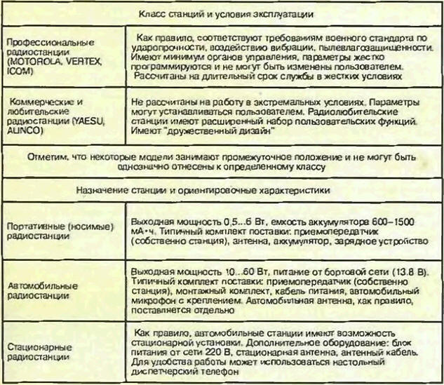
For the organization of radio communication systems, frequency ratings must be allocated. As a rule, permissions for the use of radio frequencies are issued by the State Communications Supervision Authority. Exceptions are a number of departmental communication systems, for example, power structures, which are assigned dedicated frequency subbands. But in any case, to create a communication system in the indicated ranges, it is necessary to allocate frequency ratings. 2. Types of radio equipment The radio equipment presented on the Russian market can be divided into groups according to the following categories: Professional, commercial and amateur stations, as a rule, do not differ in basic radio engineering parameters (frequency bands, output power, sensitivity). The choice of one or another type of equipment is determined by the operating conditions, the required set of functions, etc. naturally, affordable money (professional radio stations, for example, can cost twice as much as commercial ones). 3. Radio range the communication range depends on a large number of parameters (open area or city, terrain, antenna installation height, interference level, etc.) and can only be accurately determined experimentally. Approximate values of the radio communication range are shown in fig. 1.
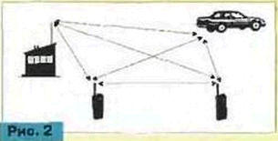
4. Frequency channels and operating modes of radio stations The vast majority of modern radio stations operate in simplex or half-duplex mode. In this case, reception and transmission are not possible at the same time. The station is switched on for transmission by pressing the PTT. When the PTT is released, the station switches to receive mode. The transmit and receive frequencies form a frequency channel and in the general case can be different. If the transmit and receive frequencies are the same, then the channel is called simplex. If the transmit and receive frequencies are different, then the channel is full-duplex, and the mode of operation of the radio stations is half-duplex. In full duplex mode (that is, when transmitting and receiving are carried out simultaneously and the PTT does not need to be pressed), only full duplex radios can operate on a duplex channel. It should be noted that almost all radio stations, regardless of the type of frequency channel, operate in simplex (or half-duplex) mode (duplex radio stations are not very common due to their high cost). The radio can be programmed with the parameters of various channels. Depending on the model of the radio station, the number of channels can vary from 1 to 100 or more. 5. Simplex radio networks The choice of the type of radio network is determined by the available frequency resource, the number of users and the specifics of their work. Let's consider the simplest option, when one nominal frequency is used (one simplex frequency). As a rule, the number of radio stations operating in this mode is small (5-25). The radio network can use portable, vehicular, and fixed radios. All of them are equal. Of course, the communication range between automobile (stationary) stations is higher. In the simplest case, all users of radio stations operating on the same frequency hear each other and call the required subscriber by voice (Fig. 2).
A fairly common option is when one of the stations is a control room (Fig. 3). This is usually a fixed station with a high gain antenna and placed high enough. At the same time, due to the correct choice of the type of antenna and its placement, the communication range with the dispatcher station increases and subscribers who are not able to communicate directly with each other can send a message through the dispatcher. In the presence of a duplex pair of frequencies, it is more rational to use a repeater). Dispatch radio networks are most often used to organize technological or service radio communications.
6. Groups of subscribers in a simplex radio network Quite often in a radio communication system it is required to divide subscribers into groups. The simplest solution to this problem is to allocate its own frequency rating to each group, which, however, is impossible in most cases due to a limited frequency resource. The most acceptable solution in this case is to separate the groups by tone or digital pilot signals (Fig. 4).
Every radio has a squelch that prevents radio noise from entering the loudspeaker (or headphones) when there is no signal. In the simplest case, the radio station's squelch is turned off when a carrier of the corresponding frequency (carrier squelch) appears on the air. In addition, almost all modern radio stations have the functions of tone (TONESQUELCH, CTCS5, PL) and / or digital (DIGITAL SQUELCH, DCS, DPL) squelch control. What is TONE SQUELCH, CTCSS, PL? The band of sound (voice) frequencies in the radio station is distinguished by a special filter and has a width of 300 to 3000 Hz, which is quite enough for intelligible speech transmission. There is also a subtone frequency band from 67 Hz to 250 Hz. Signals in this band are not passed by the audio filter and are not heard in the speaker. The pilot tone is a subtone frequency tone signal that is transmitted simultaneously by a voice signal. 49 standard tones for most types of radio equipment are allocated in the subtonal band. In the radio station, in addition to the frequency of reception and transmission, the frequency or tabular number of the tone signal is set (programmed) to be transmitted along with the sound signal in transmission mode, and the frequency or number of the tone signal, upon recognition of which in the receive mode the squelch must be opened and the sound signal fed into the loudspeaker. The transmit and receive pilots are chosen to be the same in most cases. What is DIGITAL SQUELCH (synonyms DIGITAL SQUELCH, DCS, DPL, digital pilot signal). The principle of operation of digital control systems for noise suppression is similar to tone. In the subtone band, a digital signal is transmitted (a repeating sequence of 8 bits with a carrier frequency of 133 Hz). Digital pilots are also standardized. Their number is over 100. It should be noted that tone noise reduction systems are more common and are available in almost all types of modern radio stations. Many types of radios have both tone and digital noise reduction (optional). Pilot tables in different types of radios may not match completely. Nevertheless, even when using different types of equipment, it is possible to distinguish a group of pilot signals that is the same for all stations. So, using a tone or digital noise reduction system, users can be divided into groups operating at the same frequency. Each group is assigned a different pilot tone, and radio users will only hear members of their group. This, however, does not mean that all user groups will be able to negotiate at the same time. As a rule, with such a division into groups, radio stations are programmed to prohibit switching on the transmission if there is a "foreign" pilot signal on the air. The same radio station can be a member of different groups. In this case, the corresponding pilot signals are set on different channels. The nominal frequency in this case on all channels can be the same. Note. Unfortunately, there is no single, well-established terminology for defining squelch control systems. The term "PILOT SIGNAL" was introduced as the most simple and understandable. MOTOROLA terminology: PL(Private Line)< DPL (Digital Private Line). PL and DPL are registered trademarks of MOTOROLA. International terminology: CTCSS(Continuous Tone Coded Squelch), DCS (Dltftal Coded Squelch). 7. Remote control of fixed station In some cases, for the best radio coverage of the service area of the radio network, remote installation of a dispatcher station is required. The most common solution is to use the C100 series (MOTOROLA) remote control kits. There are two options for organizing remote control of MOTOROLA GM300/GM350 fixed radios: Option 1. Local remote control (Figure 5).
It is used when the controlled station is remote from the C100 LOCAL (EN 1000) dispatcher console at a distance of up to 300 m. The C100 series remote control is similar in design to a standard telephone set, on the handset of which there is a PTT. In addition, there is the possibility - hands-free - the remote control has a built-in loudspeaker, microphone and "TRANSMIT" button. The C100 LOCAL remote control connects directly to the GM300/GM350 accessory socket. The control is carried out via a six-wire cable. The remote control is powered by 12 V. Several consoles can be connected to one radio station, but the total length of the connecting cables should not exceed 300 m. The advantage of this option is the low cost. Disadvantages - the need to lay a six-wire cable: limited range of remote control. Option 2. Tonal remote control (Fig. 6). It is used in cases where the controlled station is removed from the C100 TONE (EN 1001) dispatcher console at a distance of more than 300 m (up to several kilometers). The radio station is controlled by tone signals over a dedicated pre-wire line. A remote control tone adapter is used to decode the control tones and convert them into radio control signals. This device plugs directly into the GM300/GM350 fixed radio accessory jack. The adapter is powered from the station. The control line is connected to the adapter - on the one hand, and to the C100TONE console - on the other. From the tone remote control it is possible to switch up to two channels at the station (there are F1 / F2 buttons on the remote control). The rest of the design of the tone remote control is similar to the design of the local one.
Advantages - long range of remote control; ability to switch channels. Disadvantages - the need to use an adapter; high cost compared to the local option. Note. Channel switching is only possible with the 16-channel GM300 and 128-channel GM350 models.
8. Access to the telephone network (Fig. 7)
Even when using one simplex frequency in the radio network, access to the telephone network (usually a departmental one) can be organized. To do this, it is necessary to install a fixed radio station with a telephone interface, and portable and car stations must have a telephone (OTMP) keyboard. What is DTMF? DTMF (Dual Tone Multi Frequency) is a selective calling system used in telephony. In Russia, as you know, the most common is the pulse dialing of telephone numbers, that is, each digit is transmitted by the corresponding number of pulses. In most countries with a developed telephone network infrastructure, tone dialing is used, that is, each digit is transmitted as a pair of tone-frequency signals. This is the DTMF signaling system. The standard set of DTMF signals includes the numbers from 0 to 9, as well as the characters "#" and - "*" Radio stations with a DTMF keypad (similar to a telephone keypad) can transmit DTMF signals over the air and access the telephone network through a telephone interface. A fixed station equipped with a telephone interface receives a DTMF telephone number dialed from a subscriber station and transmits it to the telephone network. If pulse dialing is used in the telephone network, then the telephone interface converts DTMF into the corresponding signal-number in pulse form. As a rule, when using the simplest telephone interfaces without selective calling, subscribers of all stations of the radio network will hear telephone conversations (unless they are divided into groups by pilot signals). A certain pilot signal can be set on the channel where the telephone interface is used. The subscriber of the telephone network who dialed the number of the telephone interface will also call all radio subscribers or radio stations of the group simultaneously with the corresponding pilot signal. 9. Signal systems of a selective (selective) call. As indicated in the previous article, radio network subscribers can be divided into groups using tones or digital pilots. In addition, there are selective calling systems, using which you can call a specific subscriber, as well as implement a number of additional functions. It should be noted that the use of signaling systems makes it possible to implement functions at the level of subscriber radio stations without the use of complex basic equipment. The general principle of operation of selective calling systems: 1. Each radio station is assigned an individual number. 2. A group of radio stations is assigned a group number (each radio station can have an individual number and can be a member of one or more groups). 3. Depending on the type of signaling system and the equipment used, the individual and group numbers of stations are stored in memory or can be dialed from the keypad of the calling station. 4. When selecting the number of the called station from the memory cell or typing it using the keyboard of the calling station, the corresponding signal is sent on the air, which is decoded by the called station. After the signal is decoded, the called station's squelch is opened and conversations can be started. The squelch of other subscriber stations remain closed. (The procedure for calling a group is the same as calling an individual.) 5. Depending on the type of radio, paging signals can be both encoded and decoded, only encoded, or only decoded. It is possible to use various signaling systems in the mode of reception and transmission. 6. Signaling systems may be used in conjunction with pilots. 7. The use of signaling systems is focused primarily on solving professional problems. In most cases, only professional radios have the ability to use private call systems. (The exceptions are systems such as DTMF and single tone calling, which are often used in commercial and amateur radio stations.) Types of signal systems. 1. DTMF (see above). In most cases, radios are equipped with only a DTMF encoder. In the presence of a DTMF decoder, it is possible to organize a selective call. 2. Single tone call (Single Tole). An audio-band tone of programmable frequency and duration that, when decoded, opens the called station's squelch and rings. 3. Two-tone call (2-TONE, Motorola QuickCall II). Physically, it is a serial two-tone signal in the audio frequency band. There are standard tables of frequencies or tone numbers. Some types of stations provide the possibility of programming signal parameters. In most cases, radios only have the ability to decode two-tone call signals. The radio is programmed on each channel with a two-tone sequence that, when decoded, will open the squelch and ring. In the memory of a radio station that has the ability to code two-tone call signals (this is, as a rule, a dispatcher station), the numbers of subscriber stations of the radio network or groups and the corresponding two-tone signals are recorded. To call a specific radio station or a group of stations, you must select its number (the number is selected from the memory using the "up'7" down" arrows while the station is displayed on the display) and press the PTT. 4. Signal system MDC-1200 from MOTOROLA Physically, it is a digital frequency-shift keyed signal. "1" is encoded with one period of frequency 1200 Hz, "0" - one and a half periods of frequency 1800 Hz. The digital information transfer rate is 1200 bps (hence the name MDC-1200). The MDC-1200 is similar in application to the QuickCall II. An individual or group number in the MDC-1200 system corresponds to a digital signal. 5. Package of signaling systems RapidCall. The RapidCall signaling system package was developed by MOTOROLA and allows implementing a number of special functions based on the use of MDC-1200, QuickCall II and DTMF signaling systems. It should be noted that the functions of the RapidCall package are supported only by MOTOROLA radios (GP300, P110, P200, VISAR, HT1000, GM300, M208, M216). FUNCTIONS OF THE RAPIDCALL SYSTEM: - Voice Selective Call (Sel Ca11) - selective call; - Call Alert - notification of a call that came in the absence of a subscriber (indication on the display, sound signal); - PTT-ID transmission of the individual number of the radio station with each press of the PTT and display of this number on the display of the dispatching station; - External Alarm (for car radios) - notification of a call in the absence of a subscriber by turning on the car's lights or a sound signal; - Radio Check - checking the availability of radio communication without the participation of the operator. The signal is sent from the dispatcher station and decoded by the subscriber station. After that, the subscriber station automatically issues an acknowledgment signal; - Emergency Alarm - alarm signal. It is sent after pressing the "alarm" button at the subscriber station (for portable stations) or when the contacts of a special relay or pedal are closed (for car stations). The alarm signal is sent to the control station automatically and repeatedly until an automatic acknowledgment is received. The control station display shows the symbol corresponding to the alarm and the number of the radio station that sent the alarm. A typical structure of the dispatching system using the RapidCall package is shown in fig. 1. The 16-channel model of the MOTOROLA GM300 radio station can be used as a dispatcher station, and the 8- and 16-channel models of the GP300 and GM300 can be used as subscriber stations.
6. Five tone call (5-TONE, Select-5). Physically, it is a sequence of tones in the audio frequency band. The number of tones in a signal can be from 1 to 7. The name "five-tone call" reflects the structure of previous versions, where the number of tones was rigidly fixed. Each digit of the radio station number is programmed with a specific tone. This signaling system has received the greatest distribution in Europe. There are several different tone tables adopted in various European countries (CCIR, ZVEI, EEA). Depending on the type of equipment, one or another set of tones is supported. MOTOROLA radios feature the Select-5 selective calling system, which not only supports all the most common tone sets, but also allows you to create custom tables.
As a rule, the stations provide the ability to both encode and decode Select-5 signals. Number dialing can be done both from the keyboard and from the memory cell. When using the Select-5 system, functions similar to those of the RapidCall package are implemented, as well as a number of additional ones. It should be noted that many of these functions are implemented in modern trunking communication systems. In addition, in trunking systems, subscriber station management is simplified as much as possible, which cannot be said, for example, about systems using RapidCall. Nevertheless, the implementation of a large number of functions at the level of user equipment without the use of expensive base stations can be considered an undoubted advantage of such systems. RapidCall, Call Alert, Se/Call, MDC-1200, Select-5 are registered trademarks of MOTOROLA Inc. 10 Use of repeaters in radio networks So far, simplex radio networks have been considered. In the presence of two frequency ratings (duplex pair), it is possible to organize a radio network using a repeater, which can significantly increase the radio communication range. (Single frequency echo repeaters with signal recording are not considered). Repeater Features The repeater receives a signal at the F1 frequency, demodulates it, amplifies it and transmits it at the F2 frequency. The time spent on signal processing is considered negligible. The repeater is a duplex device, i.e. reception and transmission are carried out simultaneously. The transmission frequency of all subscriber stations operating through the repeater is F1, and the reception frequency is F2. At the same time, subscriber radio stations operate in the mode of a two-frequency simplex half-duplex (Fig. 2).
Duplex interval and duplex filter The repeater can use two separate antennas for transmit and receive, or one antenna and a duplex filter. The duplex interval is the difference between the receive and transmit frequencies. To exclude mutual influence, the receiving and transmitting antennas must be installed at a certain distance from each other. The value of the spatial separation has an inverse relationship with the value of the duplex interval. It is far from always possible to install antennas in such a way as to avoid mutual influence. In most cases, one transmit-receive antenna and a duplex filter are used - a device that separates the receive and transmit bands. The normal duplex interval for half-duplex operation is 4...5 MHz. At the same time, it is possible to make a duplex filter quite inexpensive and compact. In the case of a smaller or larger duplex interval, the design of the duplex filter becomes more complicated, and the price increases significantly. Repeater Duty Cycle The duty cycle of a repeater is the percentage of time it is continuously transmitting at a certain constant output power level, without the repeater failing. The duty cycle is largely determined by the transmitter's cooling system and power supply parameters. Repeater Composition The repeater usually includes a transceiver, a power supply, a controller, and a case with a cooling system. Power supply, controller, duplex filter can be built-in or external. The cooling system can be forced (radiator + fan) or passive (radiator only). MOTOROLA GR300/GR500 repeaters use GM300/350 car radios as receiver and transmitter units. Note. The principles of building only the most popular repeaters such as VERTEX VXR-5000, MOTOROLA GR300/500, KENWOOD TKR-720/820 are described above. Repeater operating modes 1. "Open repeater" In this mode, access to the repeater is not limited in any way. When a carrier appears on the air with a frequency corresponding to the reception frequency of the repeater, the signal is retransmitted. 2. Repeater with access code. Access to the repeater may be restricted. Retransmission will occur only after the programmed access signal has been decoded. In the simplest case, the repeater can be opened by an appropriate pilot signal. When using more complex controllers, the access code can be transmitted in various signaling systems (SingleTone, DTMF, MDC-1200). 3. Multigroup repeater. As in a simplex radio network, subscribers can be divided into groups based on pilot signals. The controller of the repeater uses a device, most often called TONE PANEL. The controller for various user groups records the pilot signals to be decoded, and the corresponding pilot signals to be transmitted during relaying. Each group has its own pair of pilot signals for receiving and transmitting, which in a particular case can coincide. If the repeater is occupied by one group of subscribers, other groups are prohibited from transmitting. The number of groups is determined by the controller type. A fairly popular type of multigroup repeater is the MOTOROLA GR300/500 with the ZETRON ZR310 controller. 4. Repeater with access to the telephone network. As in a simplex radio network, when using a fixed station with a telephone interface, it is possible to use a repeater with a controller that provides access to the telephone network. (For the simplest option without selective calling, a MOTOROLA GR300/500 repeater with an i50R controller can be used.) In this case, radio network subscribers can use the following call types: 1) radio subscriber - group (open radio communication, everyone hears each other); 2) radio subscriber - a subscriber of the telephone network (all other subscribers hear the conversations and can intervene); 3) telephone network subscriber - a group of radio subscribers. 5. Repeater with selective call. When using a repeater with the appropriate controller, it is possible to organize an individual or group call. Quite popular is the combination of a controller with a selective call and a telephone interface (Fig. 3).
In this case, radio network subscribers can use the following call types: 1) radio subscriber - radio subscriber (individual call); 2) radio subscriber - group; 3) radio subscriber - a subscriber of the telephone network; 4) telephone network subscriber - radio subscriber; 5) telephone network subscriber - a group of radio subscribers. One of the most popular controllers with selective call and telephone interface is ZETRON ZR320. When it is used to organize a selective call, various signaling systems can be used. The most standard option is to use DTMF as the incoming system (from the repeater/base station side). The corresponding pilot signal is used as the outgoing signal. Each subscriber station is programmed with an individual pilot signal for reception. The controller sets the correspondence table between individual DTMF numbers and pilot signals. The modes of relaying and access to the telephone network are selected by various DTMF access codes, which must be dialed from the keyboard or called from the memory cell and, having received a system readiness signal, proceed to dialing the radio subscriber or telephone number. The called station number is dialed from the DTMF keypad of the calling station. After the number is decoded in the controller, the corresponding pilot signal is transmitted on the air along with the call tone generated by the controller. Trunking systems Despite the fact that modern non-trunking systems can provide the user with a wide range of opportunities for organizing radio communications, they all have one common drawback - the inefficient use of radio frequencies. Let us explain the situation with a simple example. Suppose we have three radio frequency channels, each of which is hardwired to several user groups. At the same time, for such a system (more precisely, three separate systems), the situation shown in Fig. a: channel 1 is overloaded, at the same time channel 2 is not used. Imagine that our three channels are combined into a single system and are equally accessible to any group of subscribers. In this case, the situation will look as shown in Fig. b. It is obvious that the quality of service has increased due to the improvement in the use of channels, and we have got the simplest trunking system. Thus, a trunked radio communication system (hereinafter referred to as TCP) is a system that uses the principle of equal channel availability for all subscribers or groups of subscribers. This principle has long been widely used in telephone networks, from where the word "trunk" (a bundle, i.e. a bundle of equally accessible channels) came to radio communications. The main function of the TCP equipment that determines the name is the automatic provision of a free radio channel at the request of the radio station subscriber and switching to this channel of the called subscriber or group of subscribers. By the way, from this point of view, wireless phones (such as the PANASONIC KX-T9080) operating on a common set of radio channels also collectively form TCP. However, modern professional radio communication systems, which are discussed below, have a number of other possibilities. General Features of Trunked Systems First of all, this is an increase in the range of the system, since, even in the simplest TCP, radio stations communicate with each other through base station (BS) repeaters. In addition, multi-zone TCPs include several (from units to hundreds) BSs, each of which serves its own zone. In this case, the system will establish a connection between the radio stations regardless of their location and, as a rule, is completely transparent to the users of the called and calling radio stations. In addition to calling a group of radios (available in all TCPs), almost all systems provide individual calling to a specific radio station. At the same time, many modern TCPs provide the division of the entire fleet of radio stations into separate units. A squad is a collection of radio stations belonging to a certain organization, within which we can make an individual and group call. It is assumed that calls between units are prohibited in most cases (although they may be allowed to specific radio stations). Thus, each of the organizations using TCP can have, as it were, its own isolated communication system. As a rule, TCP provides communication between the radio station and subscribers of city and several office telephone networks, and their connection to such networks can be carried out both in the simplest way via subscriber lines (similar to office PBXs) and via connecting lines. In the latter case, in terms of subscriber numbering, TCP becomes part of the telephone network of a city or institution. Modern TCPs also provide a wide range of data transfer services between radio stations. Access to each type of service provided by the system is usually programmed individually for each subscriber. In addition, the maximum talk time and subscriber priority are programmed. TCP also have protection against unauthorized access to the system.
And when a radio station works in TCP, situations may arise in which it is necessary to do without its services (communication with a conventional radio station, BS failure, going beyond the coverage area of all BS of the system). In this case, all radios designed to work in TCP have the ability to switch to normal radio mode. Of course, this feature can be disabled during programming. The equipment of any TCP is designed for commercial operation, therefore, it necessarily provides accounting for the time the system is used by each subscriber (billing). Comparative review of trunkkin systems Currently, there are many different types of TCP that are incompatible with each other. Some of them are closed, i.e. the manufacturing company does not publish protocols of their operation and produces all subscriber and basic equipment for such systems. In this case, the consumer is completely dependent on the manufacturer. Other TCPs are open, i.e. standards for them are published, and within such systems, equipment from any manufacturer that adheres to these standards can work together. According to the method of transmitting voice information, TCP can be divided into analog, which so far includes all commercially effective TCPs, and digital. Such systems are currently offered for special services by some companies, and the new European standard TETRA is also digital. According to the principle of operation, three types of TCP can be distinguished 1. Scanning TCP Often such systems are unfairly called pseudo-trunking. In such systems, the radio station itself, when calling, looks for an unoccupied channel and occupies it. In standby mode, the radio continuously scans (scans) all the channels of the system, checking if it is being called on one of them. These TCPs include the once widespread Altai system in the USSR, as well as the SmarTrunk II system. Scanning TCPs are simple and cheap. In these systems, complete independence of the BS channels from each other is possible, since they are combined into a common TCP at the level of the subscriber radio station. This leads to high reliability and survivability of scanning TCPs. However, such TCPs have a number of fundamental drawbacks. With an increase in the number of channels, the duration of establishing a connection in such a system quickly increases, since it cannot be less than the duration of a full scan cycle. In reality, the duration of the search for a free channel of the calling radio station is also added to this. In addition, in scanning TCP, it is difficult to implement many modern requirements, including multi-zone, flexible and reliable priority system, queuing when the system or the called subscriber is busy, etc. Thus, scanning TCP is ideally suited as a small (1-8 channels, up to 200 subscribers) single-zone communication system with minimal requirements. This has led to the widespread use of SmarTrunk II systems in Russia and the CIS countries in recent years. 2. TCP with distributed control channel These are the LTR system common in the USA, developed back in the late seventies by EF Johnson, and its modern modification ESAS, offered by UNIDEN. In these TCPs, control information is transmitted continuously over all channels, including busy ones. This is achieved by using frequencies below 300 Hz for its transmission. Each channel is the control channel for the radio stations assigned to it. In standby mode, the radio listens to its control channel. In this channel, the BS continuously transmits the number of a free channel that the radio station can use for transmission. If, on any channel, a transmission addressed to one of the radio stations begins, then information about this is transmitted on its control channel, as a result of which this radio station switches to the channel where the call takes place. Such TCPs have some of the advantages of a TCP with a control channel, while at the same time not requiring a frequency allocation for it. In the LTR system, the connection is established so quickly that it is established every time the station transmitter is turned on, i.e. during conversation pauses, the channel is not busy. However, if any channel fails in the LTR system, all radios for which it is the master will fail. In addition, in such TCPs, the transmission rate of control information is extremely limited. This makes it difficult to implement many of the requirements for modern TCP, including multizone. The transmission of information at frequencies below 300 Hz simultaneously with speech makes such systems very critical to the accuracy of the adjustment. All this has led to the fact that TCP with a distributed control channel is not currently being developed. The only exception is ESAS, which uses this principle for the sake of compatibility with LTR. 3. TCP with dedicated control channel For analog systems, we are talking about a frequency channel, for digital - with time division of channels - about a time slot. In such TCPs, the radio station continuously listens to the control channel of the BS closest to it. When a call arrives, the BS transmits information about this via the control channel, the called radio station confirms the receipt of the call, after which the BS allocates one of the conversational channels for the connection and informs all radio stations participating in the connection about this via the control channel. After that, they switch to the specified channel and remain on it until the end of the connection. While the control channel is free, radios can send their connection requests there. Some types of calls (for example, the transmission of short data packets between radio stations) can be carried out without occupying the conversational channel at all. TCP with a dedicated control channel is the most up to date. They easily implement multi-zone (the radio station selects the BS with the best received control channel) and other functions.
Among them - the queuing of calls when the system or the called subscriber is busy. This, in turn, moves such TCPs from the class of systems with refusal on busy to the class of systems with waiting. Thus, not only the comfort of the user's work is increased, but, most importantly, the throughput of the system is increased. In Busy Denial systems, at least one channel must be idle at any given time to ensure acceptable quality of service for the subscriber to make a call. In a waiting system, all channels can be loaded. In this case, however, the caller will have to wait a little in the queue. However, the allocation of a separate control channel has its drawbacks. Firstly, this is the worst use of the frequency resource. In most systems, this drawback is mitigated by the ability to switch the control channel to conversational mode when the system is overloaded. Secondly, a dedicated control channel is a TCP vulnerability - in the absence of special measures, the failure of the BS equipment for this channel means the failure of the entire BS. The appearance of interference at the frequency of the BS control channel receiver also leads to the same result. For this reason, when developing TCP with a dedicated control channel, special attention is paid to automatic control over the operation of BS equipment. When a failure or long-term interference is detected at the receive frequency, the BS makes another, serviceable channel the control channel. A dedicated control channel is provided by most modern standards for TCP - both closed and open (MPT1327), as well as the promising TETRA standard. For comparison, the table shows the characteristics of some TCPs. It should be clarified that the table shows the characteristics laid down in the standards. Plain TCP hardware often allows these features to be extended (multiple channel banks in SmarTrunkll, multi-zone operation in LTR, etc.). As can be seen from the table, the TETRA standard has the most impressive capabilities. This is not surprising - it was developed taking into account the experience of operating existing TCPs. Unfortunately, for the TETRA system at present there are only experimental models of equipment, and it is too early to talk about their commercial operation and, moreover, about commercial efficiency - the prices for such equipment will remain high for a long time to come. Currently, the most effective systems in Russia are SmarTrunkll and MPT1327. Firm "Electronics-Design" is actively engaged in the installation of these TCPs, as well as the development of additional equipment for them. Author: B. Prokhovnik, "Electronics-Design" Moscow. Phones: (095) 165-1892,165-0874 E-mail: eldiz@dol.ru
The world's tallest astronomical observatory opened
04.05.2024 Controlling objects using air currents
04.05.2024 Purebred dogs get sick no more often than purebred dogs
03.05.2024
▪ Processor Intel Core i9-13900KS ▪ Cells increase in volume when tissues are bent ▪ Fullerene balls in the energy sector ▪ Two-channel DC/DC converter for powering screens of portable devices
▪ site section Clocks, timers, relays, load switches. Article selection ▪ article Shine with your absence. Popular expression ▪ article Stonecrop white. Legends, cultivation, methods of application ▪ article Power amplifier for CB radio. Encyclopedia of radio electronics and electrical engineering
Home page | Library | Articles | Website map | Site Reviews
www.diagram.com.ua |


 Leave your comment on this article: