|
|


 Arabic
 Bengali
 Chinese
 English
 French
 German
 Hebrew
 Hindi
Hindi Italian
 Japanese
 Korean
 Malay
Malay Polish
 Portuguese
 Spanish
 Turkish
 Ukrainian
 Vietnamese
|
ENCYCLOPEDIA OF RADIO ELECTRONICS AND ELECTRICAL ENGINEERING Transmitting complex of individual radio broadcasting. Encyclopedia of radio electronics and electrical engineering
Encyclopedia of radio electronics and electrical engineering / Civil radio communications More than nine years have passed since February 2006, when the article [1] was published - the first one with a proposal to introduce into the framework of the legal field the long-standing passion of young people for informal radio broadcasting - more than nine years have passed. In November 2009, a conference dedicated to individual broadcasting was held. For the first time, informal radio broadcasters themselves, representatives of Rospechat, the Ministry of Communications, the Main Radio Frequency Center (GRC), and the Russian Television and Radio Broadcasting Network (RTRS) sat down at the same table for a constructive conversation. Teachers from technical universities were also present, primarily interested in teaching radio engineering only to those school graduates who consciously chose their future profession in the field of radio engineering, broadcasting and radio communications and, while still at school, were already engaged in practical radio design on their own or in radio circles. During the conference, the first legal AM radio station of individual broadcasting "Green Eye" or "Magic Eye" (meaning the eye of the 1602E5995C lamp), registered in accordance with the current legislation, worked on the air at frequencies of 6 kHz and 5 kHz. All the programs of informal broadcasters sent in recordings, which could personally conduct the author's radio program under their own callsign, sounded on the air. In 2012, at the initiative of the Tyumen Club of Individual Radio Broadcasting (Radio "Vektor - Tyumen", 1575 kHz) and with the support of the Ministry of Communications and the GRFC, the first competition for the design of home-made broadcasting transmitters was held. All its participants from 17 cities of Russia were provided with radio frequencies in the 200-meter medium wave band for broadcasting and in the 90-meter short wave band (3370 kHz, 6K80A3E) for the exchange of spoken programs and radio communication for testing the assembled structures. Roskomnadzor has issued temporary semi-annual permits for the release of self-made radio transmitters on the air. Since July 2012, the student radio station of the Moscow Technical University of Communications and Informatics "Radio MTUCI" began regular broadcasting in the medium wave band (1584 kHz) and in the 11-meter broadcast HF band (25900 kHz) and almost simultaneously - the student radio station of St. Petersburg University telecommunications them. M. A. Bonch-Bruevich "Radio Bonch" (1593 kHz). The main task of the individual radio broadcasting project is to captivate young people with radio engineering, guide schoolchildren to choose their future profession in the fields of radio engineering, radio communications and broadcasting, train technical and engineering personnel with practical skills and deep knowledge in the field of radio engineering. Therefore, all links in the functional chain of individual radio broadcasting should in principle be self-made, or better, independently developed, but, of course, comply with the standards of the State Committee for Radio Broadcasting for professional broadcasting equipment. This is a radio engineering project, and it is aimed exclusively at training competent radio engineers. The use of industrial transmitting equipment in individual broadcasting destroys the very essence of the project, the very idea of practical study of radio engineering and attracting young people to it, and turns it from engineering and radio engineering into journalistic and DJing. Going on the air is a bonus for a techie who independently assembled a broadcast radio transmitter, this is the joy of creativity, inspiration from the realization of the fruits of his hands. And if there are no fruits, then there is no bonus. Therefore, we take a soldering iron. After all, everything shown in Fig. 1, to be done by yourself. Better yet, develop it yourself.
This article is devoted to the description of the functional composition of the transmitting radio path for individual broadcasting, the appointment of all its structural units and recommendations for their future development, not only by the author of this initiative, but also by all interested radio engineers, individual radio broadcasters and radio amateurs. In table. 1 shows the list of basic requirements for individual broadcasting transmitters developed by the author on the basis of documents [2] and [3]. They must be followed during the development, manufacture and operation of such transmitters. Table 1
Notes: 1. MF transmitters for individual broadcasting must operate strictly in the broadcasting frequency grid with a step of E kHz. The ability to set the controls to another frequency is unacceptable. 2. See Decision of the SCRF dated 24.05.13 No. 13-18-03. 3. Measured on a resistive load of 50 or 75 ohms at a modulation depth of 70%. 4. Provided by setting the matching device. The broadcast starts in the broadcast studio. In the centers of scientific and technical creativity of youth (NTTM) and children's technical creativity, in technical universities and colleges, this can be a separate room, equipped according to all the canons of acoustics and equipped with the most advanced studio equipment, for example, as described in articles [4, 5]. In amateur radio circles and at home, an on-air studio can be equipped in a small nook, on the walls of which a carpet hangs behind the leader for soundproofing, a microphone is mounted on a bracket, and an on-air mixing console is on the coffee table. It is also possible to have a studio without such a console, when all its functions are performed by the on-air computer software. In this case, the computer system unit with its noisy fans must be moved outside the sensitivity zone of the on-air microphone or a special noise-resistant dynamic microphone Shure SM7B should be used [6]. In general, it is better to use dynamic microphones for individual radio broadcasting. Condenser microphones are not recommended for use in home and other non-absorbent "studios" due to their susceptibility to background noise. With any variant of equipment of the on-air studio, a bi-phase stereo signal with a level of 0 dBm (0,775 Veff at a load of 600 Ohms) should be received at its output. Since the studio complex is located in close proximity to the radio transmitter and transmitting antenna, it is necessary to take care that the on-air console has input filters for radio interference suppression, so that it is shielded, and all interconnecting audio circuits are made symmetrical with respect to the common wire by twisted pairs of wires in the shield. The use of unbalanced connecting lines (single wires in the screen) is not allowed in this case. Electric guitarists should pay special attention to this. As a rule, the outputs of cheap mass-produced pre-amps for electric guitars and guitar sound processing devices are unbalanced. When you try to connect them to the on-air remote control, pickups from the transmitter can lead to self-excitation of the equipment or to severe sound distortion. Homemade guitar "gadgets" also suffer from the same drawback. Combiner of stereo signals. Since AM broadcasting is monophonic, the stereo signals coming from the on-air studio (and all studio equipment is produced in stereo) have to be converted to monophonic, summing both stereo channels. The adder can be made either with resistors or with an operational amplifier. I draw your attention, if you want to get a natural "live" sound, add analog signals. Digital technologies are superfluous here. As a rule, the stereo channel adder is part of the AM processor. But if this processor is software, then the stereo channel adder must be part of the transmitter modulator. On the block diagram shown in fig. 1, they must be equipped with the UMZCH input. AM processor - a very complex device used exclusively in broadcasting. It has several tasks: - pre-correction of frequency distortions introduced by the transmitter modulation path; - reduction of the peak factor of audio signals, which improves their intelligibility in the noise of the air, and also increases the average depth of the transmitter modulation; - creation of an individual intonational portrait of the radio station; - creating a timbre of the sound of radio programs that is pleasant for listeners; - preparation of the modulating signal to limit its frequency band to 50...8000 Hz. The simplest implementation of an AM processor is a multiband compressor (seven or eight frequency bands ranging from 50 to 8000 Hz) with different compression settings in each band. The frequency boundaries of the bands are set rigidly either by filters of the same Q factor (in this case, there will be seven bands), or by filters with a Q factor that increases linearly with an increase in the center frequency (in this case, there will be eight bands). The latter allows, with a monotonous phase characteristic, to more accurately build the timbre curve of the output signal. The lower, middle and upper frequencies of the seven-band processor filters are shown in Table. 2. Their meanings are chosen according to the provisions of psychoacoustics. They make it possible to regulate the intensity and saturation of sound vibrations of different frequencies, responsible in the associative perception of a person for certain emotions and moods. Seven frequency bands with different compression in each is the minimum number at which it is possible to highlight the features of the female and male voice and intonation of speech, make the sound pleasant or annoying, affectionate, gentle or cold, pacifying or disturbing, trusting or causing doubts in what is heard. Table 2
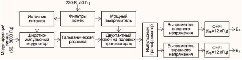
LPF with a cutoff frequency of 8 kHz. The bandwidth of the transmitted sound signals 50...8000 Hz is chosen in accordance with the characteristics of the perception of sounds by human ears, the provisions of psychoacoustics. It is sufficient to reproduce the sound of most musical instruments and vocals naturally. In broadcast radio stations in the ranges of long, medium and short waves, it is realized by 16K0A3EGN radiation. On the air, such a signal occupies a bandwidth of 16 kHz. For the same reasons, in the ranges of long and medium waves for broadcasting radio stations, a grid of operating frequencies with a step of 9 kHz was chosen (a guard interval of 2 kHz when placing radio stations in two grid steps is 18 kHz). Outside the bandwidth of the low-pass filter, a sharp drop in its frequency response should be provided with attenuation of at least 46 dB at a frequency of 9 kHz, where the carrier of any distant radio station may be located. This is achievable with a Cauer LC filter of at least sixth order. Audio frequency power amplifier (UMZCH) must provide an average output power of 15 ... 20% of the output power of the transmitter and approximately 70% of this power - peak. If the UMZCH is made on lamps [7-10], then the transformation ratio of its output transformer must be chosen so that at the modulation peaks the output voltage of the UMZCH could increase without distortion by 1,8 ... 2 times. In the case of using UMZCH on transistors or integrated circuits, its power should be equal to 70% of the output power of the transmitter. Given this feature, it is reasonable to consider the option of building an UMZCH for a modulator with a push-pull transformer output stage on "current" television lamps and with preliminary stages on integrated operational amplifiers and transistors. For transmitters with power up to 50 W, 6P14P (EL84) lamps are quite suitable, and for more powerful ones - 6P3S (6L6GC, 5881 and KT66). Voltage adder sums the supply voltage of the anode and the screen grid of the lamps of the output stage of the transmitter with the modulating voltage. There are both serial and parallel summation schemes. The serial one is simpler and contains fewer elements, but at the same time, the modulation transformer works with bias and a voltage develops on it that reaches double, and at idle and triple the constant anode voltage. Such modulation transformers, made by radio amateurs at home, are prone to breakdowns that can cause serious damage to the transmitter structure, up to a fire. Parallel summation requires twice as many winding products, but does not have the listed disadvantages. Moreover, it allows the use of unified chokes and transformers, commercially available and commercially available. Article [11] is devoted to a detailed description of such a modulator and the methodology for its calculation. Source of power the anode and screen grid of the lamp of the output stage of the transmitter can be transformer or pulsed. Its power must be sufficient to power the output stage of the transmitter and, possibly, the UMZCH. To power low-power nodes, another source should be used, since this one, subject to the strongest load changes during modulation, cannot provide the voltage stability necessary for these nodes. With a modulator power of 100 W or more, it suggests combining the power supply of the output stage of the transmitter, UMZCH and the voltage adder into a switching power supply with output voltages that change according to the modulation law. On fig. 2 shows a possible block diagram of such a source.
The modulation signal, which has passed the low-pass filter with a cutoff frequency of 8 kHz, is fed to the pulse-width modulator. From its push-pull output, through a galvanic isolation unit, two sequences of rectangular pulses shifted by half a repetition period with a duty cycle adjusted according to the modulation law arrive at a push-pull key on powerful field-effect transistors. The amplitude of these pulses, taken from the outputs of the keys, is increased using a pulse transformer to the values necessary to obtain the anode and screen voltage. Then these impulses are rectified. Due to the lack of sufficiently high voltage fast rectifier diodes, it may be necessary to divide the secondary windings of the pulse transformer into several sections and provide separate rectifiers for these sections. The required anode and screen voltage is obtained in this case by adding the rectified voltage of several sections. The task of the output low-pass filter is to suppress interference, the frequency of which lies near the conversion frequency and its harmonics, without distorting the frequency response of the modulation path. Therefore, the cutoff frequency of these low-pass filters should be at least one and a half times higher than the maximum modulation frequency. The conversion frequency must be chosen high enough so that the low-pass filters can effectively suppress it by at least 70 dB. To reduce combination noise, the master oscillator of the converter must be synchronized with the synthesizer of the transmitter's operating frequency. When using the synthesizer described in [12], the conversion frequency can be 45 or 90 kHz. Although such a modulator seems too complicated today, its development is quite accessible to highly qualified radio amateurs, not to mention radio engineers who are not averse to picking up a soldering iron at home. Indeed, in every computer there are almost the same devices - switching power supplies with a power of several hundred watts. They are reliable and mass produced. It is only necessary to well decouple the signal circuits from powerful transistors with optocouplers and wind a pulse step-up transformer with good insulation between the windings. True, such a pulsed source-modulator will have to screen and filter the input and output circuits very well. Operating Frequency Synthesizer should ensure its relative stability not worse than 2 10-6, installation accuracy is not worse than 5 Hz, tuning in 9 kHz steps in the range of 1449 - 1602 kHz. The synthesizer described in [12] was designed specifically for this. It has a powerful two-phase output (60 V, 0,4 A) and does not require preliminary signal amplification stages when building AM transmitters up to 100 W in carrier mode. Currently, the author is developing a synthesizer with a powerful four-phase output (100 V, 2 A), designed for broadcast transmitters with a power of up to 500 W. It has a separate highly stable (5 10-7) an exemplary generator, which is described in [13]. Transmitter output stage can be performed on "current" beam tetrodes 6P31S, 6P36S, 6P41S, 6P43P, 6P44S, 6P45S or on ceramic-metal tetrodes 6P37N-V, GS-36B, GU-74B in pulsed modes of classes D and Finv using a parallel anode power supply and double P -contour as an oscillatory system. The most complex node of the output oscillatory system of the transmitter is the inductor. The article [14] details how to make such a coil literally from improvised means that a radio amateur always has. The output stages of the synthesizers mentioned above are designed for pulsed excitation of the listed radio tubes through the cathode circuit. In the first case, two lamps open in turn (two-phase summation of power in the anode circuit), in the second case, four lamps (two-phase two-cycle summation). The use of lamps in the output stage of a broadcast transmitter is due to the need for its long-term operation in all weather conditions, including during strong winds, thunderstorms and in the presence of high potentials of static electricity on the antenna and high-voltage impulse discharges. When using transistors, very complex systems are needed to protect them from adverse factors, while using lamps, the transmitter is greatly simplified. Amplitude modulation is performed in the output stage of the transmitter by changing the anode and screen voltage. This method is simple and the most energetically favorable. The physics of operation and practical calculations of the output stages of transmitters with anode-shield modulation are considered in detail in [15]. Antenna matching circuit. Its first task is to compensate the reactive component of the input impedance of the antenna with the help of an extension inductor connected in series with it and a "garland" of capacitors, the taps from the connection points of which can be switched. To compensate for the capacitive component, the extension coil is included in the circuit, and to compensate for the inductive component, it is excluded from it. In both cases, compensation is performed by switching the string capacitors. Step matching is quite acceptable here, since the quality factor of the antenna circuit is low, and the remaining "small things" are chosen by the P-circuit. The second task is the transformation of the active component of the input impedance of the antenna into the optimal load impedance of the output stage of the transmitter. To do this, use a multi-position capacitive voltage divider installed at the output of the P-loop as its output capacitor. Fine tuning is performed by a variable input capacitor of the P-loop. Since the range of antennas used on medium waves in amateur conditions is small, a capacitive divider with no more than six taps will ensure operation with antennas having an active component of the input impedance of 18, 30, 50, 75, 150 and 300 ohms. This construction of the transmitter output has an interesting property. As a result of the redistribution of current between the output capacitance of the voltage divider and the load resistance, when connected to the "18 Ohm" terminal of a load divider with a lower active resistance (up to 8,3 Ohm), the output power remains almost unchanged. The device, as it were, adjusts itself to the load. The effect manifested itself in the calculation of the matching circuit, then was confirmed by computer simulation and tested on a real transmitter. Antenna tuning indicator it is necessary to control the tuning of the output oscillatory system of the transmitter to the operating frequency and to tune the matching circuit with the antenna to the maximum output power. It consists of an antenna RF current transformer, a detector and an indicator itself. Since it is not necessary to accurately measure the antenna current and transmitter output power (and this is impossible if the antenna radiation resistance is not known exactly), it makes no sense to use measuring instruments. We need ease of observation of indications and their visibility on the principle of "more-less". Electronic light tuning indicators - radio tubes 6E5S, 6E1P or their foreign counterparts EM11, EM84 do a good job with this task. The design of the measuring transformer and indicator, specially designed for individual broadcasting transmitters, is described in [16]. Antenna-feeder system. In the ranges of medium and long waves in radio broadcasting, radio waves of vertical polarization are used. It is quite difficult to implement antennas with pure vertical polarization of radiation in domestic conditions. Few people can pull a 50 m long wire strictly vertically away from surrounding objects and buildings. Therefore, most non-professional medium wave antennas have a mixed polarization, with a predominance of horizontal. It is very convenient to use steel-copper wire BSM-1 with a diameter of 2,5 to 4 mm (optimally - 3 mm) as a material for the wire cloth of the antenna and its counterweights. It combines the tensile strength of steel and the high electrical conductivity of the surface layer of copper with a thickness of 0,15 ... 0,25 mm. Due to the skin effect, high-frequency current flows over the copper surface of the wire, and its steel core does not spoil the operation of the antenna. Here, for example, are antenna options that are advisable to install in a city or in a suburban area: - flat inclined beam (angle less than 40о) - a wire 35 ... 50 m long, thrown onto a nearby tall tree. Grounding - a bucket buried in the ground or an iron barrel, a steel casing pipe of an aquifer or an iron fence around the site. The reactive component of the input resistance is capacitive. Active - in the range of 10 ... 20 Ohm; - steep inclined beam (angle more than 60о) - a wire 50 or even 70 m long, fixed to the corner of a neighboring high-rise building or to a high pipe of a local boiler house. Grounding - a steel pipe of the water supply system of a holiday village buried in the ground. The reactive component of the input resistance is inductive. Active - in the range of 30 ... 60 Ohm; - a horizontal "three-tail" 45...50 m long between the roofs of neighboring five-story buildings - a three-wire beam diverging in a narrow fan from the power point. Grounding - to the ground loop of the building or to the water pipe system. The reactive component of the input resistance is close to zero. Active - about 20 ... 30 Ohm; - inclined "three-tailed" 45...50 m long (angle 40...50°) from the roof of a five-story building to the roof of a 17-22-story building. Several horizontal counterweights to neighboring five-story buildings. The reactive component of the input resistance is close to zero. Active - about 30 ... 50 Ohm; - a telescopic pin 24 m high with a capacitive "asterisk" of eight beams of 3 m each at the end. Grounding - to the grounding contour of the building and several horizontal counterweights of 50 m each. If the antenna is on the ground, then the ground is four three-inch steel pipes 3 m long, dug into the ground vertically at the tops of a 10x10 m square with the antenna in the center and connected diagonally with wide copper tapes. Deep pits for pipes are made with a garden drill with an extended handle. The reactive component of the input resistance is capacitive. Active component - 12...18 Ohm; - a horizontal, slightly sagging wire 85 ... 100 m long, stretched over a neighboring building. Suspension height - 20 ... 25 m. Grounding - grounding contour of the building or a system of water pipes. The reactive component of the input resistance is inductive, not more than 150 ohms. Active component - 200...300 Ohm. In fact, the active component of the input impedance of a half-wavelength vibrator antenna, powered from the end, in free space should reach several kiloohms. But due to the low location (less than λ/8) and the influence of the earth, it will not be more than 300 ohms. This list goes on. But in any case, the active and reactive components of the input impedance of more or less efficient antennas will not exceed 300 ohms in absolute value, and the active component will not fall below 12 ohms. All of the mentioned antennas have in common that they are connected to the "Antenna" terminal of the transmitter directly or with a short piece of wire. They don't have a feeder. Of course, in this case, the transmitter chassis must be grounded or a counterbalance system must be connected to it. However, it should be possible to connect to the load transmitter with a coaxial feeder with a characteristic impedance of 50 or 75 ohms. Output power and spurious measurements should be carried out in a coaxial path. Those who wish can simulate these antennas using the MMANA program, setting the soil conductivity to 4 mS/m for the city and about 10 mS/m for rural areas in the Central Russian zone. If there is a swamp or shallow groundwater nearby, you can safely take from 20 to 50 mSim/m. Counterweight system and grounding - an integral part of the medium wave transmission complex. First, about counterweights. At medium waves, it is traditionally customary to call their active vibrators antennas, since they are all very extended and wire. At the same time, it is often forgotten that the vibrator itself cannot radiate, and the electromagnetic field unfolds in the near zone between the vibrator and counterweights. It is not superfluous to recall the importance of counterweights once again. For effective radiation, the counterweights must be resonant (λ/4 long), located horizontally or obliquely at a slight angle downwards from the feed point of the antenna. For example, if the antenna feed point is located on the roof of a five-story building, then the counterweights can be lowered from the roof down at an angle of 10...30о. At the ends of the counterweights, when the transmitter is operating, there is a high high-frequency voltage (the neon lamp next to them burns brightly). Therefore, they must end with garlands of at least three insulators and through them be attached with braces to low poles, trees or roofs of one-two-story buildings located within a radius of 50 ... 80 m from the base of the antenna. It is strictly forbidden to use structural elements of power lines as supports for mounting antennas or counterweights. It's life-threatening. The more counterweights, the lower the high-frequency voltage at the end of each of them and the lower the losses in the antenna system. Ideally, an effective transmitting antenna should have six to eight counterweights. But sometimes two is enough. Now about grounding. It protects the transmitter and its operator from high static and impulse voltage (up to 250000 V on long wire antennas) that occurs during strong winds and lightning discharges. In addition, by acting as a counterweight, grounding increases the radiation efficiency. Grounding of the equipment housing ensures electrical safety in case of possible breakdowns of the insulation of supply and other high-voltage circuits. One of the possible options for grounding is discussed in great detail in the article [17]. There are four ways to implement ESD and atmospheric discharge protection functions: 1. Use the inductive coupling of the antenna with the oscillating system in the transmitter, the second output of the coupling coil must be connected to the "Ground" terminal. 2. Connect the "Antenna" terminal to the "Grounding" terminal with a choke having an inductive resistance at the operating frequency 10 ... 15 times greater than the radiation resistance of the antenna. The inductor must ensure that static charges drain from the antenna. In practice, it is enough to wind it with a PETV-0,5 wire. 3. Connect between the "Antenna" and "Ground" terminals of the transmitter a shunt resistor, for example MLT-2, with a resistance of 20...30 kOhm. This solution is acceptable for transmitters with a power of up to 10...15 W, operating on low-lying antennas. For example, if the antenna is installed below the roofs of high neighboring buildings, they act as lightning rods. The resistor protects well against static charges, but is not always effective against impulse pickups in close lightning discharges. 4. Install a surge arrester between the "Antenna" and "Ground" terminals of the transmitter, the breakdown voltage of which is lower than the rated voltage of the output isolating capacitor. Taking into account the dielectric strength of air 3000 V/mm, at the rated voltage of the capacitor 2500 V, the gap in the arrester should be no more than 0,8 mm. It is desirable to use a spark gap with a large number of parallel spark gaps, as was done, for example, in Morse telegraph machines, which worked in the USSR in railway transport until the mid-60s (Fig. 3).
Monitor your transmitter - a loud-speaking detector receiver tuned to the operating frequency of the broadcast. It feeds on the energy of the transmitting antenna field and starts working automatically when the transmitter is turned on. Required to control the quality of the signal that went on the air. The Media Law requires recording and storing copies of all broadcasts broadcast for a month, and in the case of using a radio station for individual broadcasting to notify the public when an emergency is eliminated, for a year. So a monitor is essential. One of its variants is described in the article [18]. Recommendations are also given on its installation and use for control recording of radio broadcasts. Radio control recorder can be either an independent industrial device or a program on a computer that works for recording in parallel with broadcasting through a second sound card. The main thing is that all the radio programs made in a month fit in his memory. It makes sense to record a broadcast AM signal in one mono channel with 16-bit digitization at a quantization frequency of 22,05 kHz. Literature
Author: S. Komarov
Artificial leather for touch emulation
15.04.2024 Petgugu Global cat litter
15.04.2024 The attractiveness of caring men
14.04.2024
▪ Climate change causes bees to deform ▪ Christmas decorations make us happier ▪ Bridge made of water in an electric field ▪ Smart antibacterial water heater Xiaomi Mijia Smart Kitchen Treasure 7L S1
▪ section of the site Funny puzzles. Article selection ▪ article of state of emergency of regional scale. Popular expression ▪ article Nymphaeum shield-leaved. Legends, cultivation, methods of application
Home page | Library | Articles | Website map | Site Reviews
www.diagram.com.ua | ||||||||||||||||||||||||||||||||||||||||||||||||||||||||||||||||||||||||||||||||||||||||||||||||||||||||||||||||||||||||||||||||


 Leave your comment on this article: