|
|


 Arabic
 Bengali
 Chinese
 English
 French
 German
 Hebrew
 Hindi
Hindi Italian
 Japanese
 Korean
 Malay
Malay Polish
 Portuguese
 Spanish
 Turkish
 Ukrainian
 Vietnamese
|
ENCYCLOPEDIA OF RADIO ELECTRONICS AND ELECTRICAL ENGINEERING VHF / MW radio receiver in the housing of the subscriber loudspeaker. Encyclopedia of radio electronics and electrical engineering
Encyclopedia of radio electronics and electrical engineering / radio reception In the 70-90s of the last century, small portable black-and-white TVs with universal power supply both from a 230 V AC network and from independent 12 V DC sources were popular. By now, such TVs are morally and physically obsolete, and if malfunctions, they are usually thrown away or dismantled for spare parts. Some models of such TVs contain separate functional modules that can not be disassembled, but used for their intended purpose in home-made designs, which can speed up and simplify the development and assembly of new devices. The compact black-and-white TV model Watson SF1411 contained a separate VHF-FM / MW-AM radio receiver module (Fig. 1), assembled on a 65x90 mm board using an integrated circuit CD22427CP (similar to KA22427C) and two SS9018 transistors. This module is labeled T9050B-5. The range of received frequencies in the VHF range is 66 ... 108 MHz, in the MW range - 530 ... 1600 kHz. Radio tuning is carried out using a variable capacitor. After checking the operability of this module, it was decided to make a stationary dual-band radio receiver based on it. Although domestic radio broadcasting in the CB band is practically curtailed, this band is left "just in case".
The scheme of the device is shown in fig. 2. The radio receiving module is marked as A1. It was decided not to use the UMZCH built into the CD22427CP chip; instead, a more powerful and high-quality UMZCH was made on the TDA2003 integrated circuit. After disconnecting the dynamic head from the built-in UMZCH of the CD22427CP microcircuit, a significant improvement in the quality of radio reception was a surprise, possibly due to the elimination of the influence of the built-in UMZCH on the operation of its high-frequency nodes.
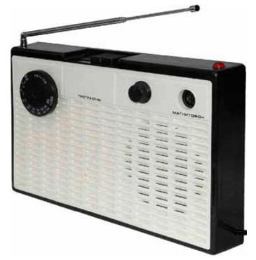
When the contacts of the switch SB1.1 are closed, the A1 module operates in the VHF band, when open, in the MW band. When the contacts of the switch SB2.1 (local/remote reception) are closed, the sensitivity in the MW range increases. The IN input of the UMZCH built into the microcircuit was connected to a common wire. The supply voltage of 8,5 V is supplied to the + V contact, the current consumption is about 17 mA. The WA1 VHF whip antenna is connected to pin A. The design provides for the radio to work both with it and with an external VHF antenna, for example, a television one, which is connected to the XW1 socket. The arrester FV1 protects the radio input from high voltage pulses, the capacitors C1, C2 are separating. AF signal output - OUT contact. During preliminary tests of the operation of the radio receiver in the VHF band, the following features were revealed. The sensitivity in the high-frequency part of the VHF range turned out to be several times higher than in the low-frequency part. And the overall sensitivity is worse than that of simple radio receivers assembled on the K174XA34 chip with an additional UHF input. But, unlike the latter, this radio turned out to be practically insensitive to interference from a nearby working computer. In comparison with the domestic radio receivers "Ocean-209" and "Ocean-214", it showed a significantly better quality of radio reception, but slightly worse selectivity. From the movable contact of the volume control R6, through the isolation capacitor C12, the AF signals are fed to the UMZCH input - the DA1 microcircuit. The voltage gain of the microcircuit depends on the ratio of the resistances of the resistors R9 and R10. Circuits R8C13 and R11C20 prevent possible self-excitation of the DA1 chip at ultrasonic frequencies. Dynamic head BA1 is connected to the output DA1 through coupling capacitors C18 and C19. The maximum output power of the manufactured UMZCH at a load with a resistance of 8 ohms is about 2 W, which is about seven times more than the UMZCH node built into the CD22427CP chip. The XS1 "Tape Recorder" jack can be used to send a signal from the output of various external devices, such as mobile devices. Resistors R2 and R3 sum the stereo signals of both channels, capacitor C4 prevents radio frequency signals from entering the UMZCH input. When contact SB1.2 or SB2.2 is closed, the UMZCH input receives a signal from the output of module A1, when contact SB3.1 is closed, signals from an external source. The mains voltage is supplied to the primary winding of the transformer T1 through the closed contacts of the SA1 switch, the FU1 fusible link and the R4R5C3 RC filter, which suppresses interference penetrating the network. In addition, resistors R4 and R5 significantly reduce the likelihood of damage to the primary winding of the transformer at increased mains voltage. The total resistance of these resistors should be approximately equal to the active resistance of the primary winding of the transformer. An alternating voltage of 11 V from the secondary winding of the transformer T1 is supplied to a bridge diode rectifier assembled on a VD1 diode assembly. Capacitors C7-C9 smooth out the ripple of the rectified voltage. The HL1 LED indicates that the device is on. Module A1 is powered by a stabilized voltage of 8,5 V from a stabilizer assembled on elements VT1, R7, VD2, C15 and C16. The A1 module remains operational when the supply voltage drops to 3,9 V. When the supply voltage fluctuates, the tuning to the radio station does not go astray, which made it possible to use a simple parametric voltage regulator, rather than an integral one. UMZCH on the DA1 chip is powered by unstabilized voltage from the output of the rectifier. Fixed resistors OMLT, MLT, RPM, S1-4, S1-14, S2-14, S2-23 or similar are used. Resistors R4, R5 it is desirable to use imported non-flammable. The variable resistor R6, combined with the switch, is SP3-12K, its contacts are connected in parallel. It can be replaced, for example, with a resistor SP3-33-20 or another resistance of 47 ... 150 kOhm, the switch contacts of which are designed for switching the mains voltage. The screen of the variable resistor is connected to a common wire at the connection point of the resistor R6. But you can use a separate power switch. Capacitor C3 is a film capacitor with a capacity of 0,047 ... 0,1 μF, designed to operate at an alternating voltage of at least 250 V. Capacitors C1, C2, C4 and C13 are ceramic K10-17 or similar imported ones. Oxide capacitors - K50-35, K50-68, K53-19 or imported analogues. The remaining capacitors are non-polar film. Capacitor C17 is installed as close as possible to the pins of the DA1 chip. The KTs405E diode bridge can be replaced by any of the KTs402, KTs405, KTs412, RB151-RB157, RC201-RC207, RS201-RS207 series. Instead of the BZV55C-9V1 zener diode, 1N4739A, TZMC-9V1, KS191A, KS191Zh, D814B1 are suitable. The 2SD2172 transistor can be replaced by any of the SS8050, 2SC2331, 2SC2500, KT646, KT684, KT6114 series. The TDA2003 chip is mounted on a ribbed duralumin heat sink with a cooling surface area of about 44 cm2. This chip can be replaced by any of K174UN14, L142, LM383, LM2002, TDA1410H, TDA1420H, TDA2002, TDA2008, ULN3701Z, ULN3702, ULN3703. The transformer is imported with an overall power of about 8 watts. You can use a unified transformer TP8-3-220-50, the secondary windings of which are connected in parallel, or TP114-4. The shield for the transformer is made of 0,5 mm thick sheet metal. The author used a tinned plate of the screen-case from a faulty monitor LCD matrix. You can also use food tin. This screen must be isolated from the transformer magnetic circuit, for example, with electric cardboard, varnished cloth or several layers of adhesive tape. The screen is connected to a common wire, the connection point is socket XW1. Pin 3 of the DA1 chip and the corresponding pin of the dynamic head BA1 are connected to the capacitors C7-C9 with separate wires. Pushbutton switch with dependent fixation - P2K, free groups of contacts are connected in parallel. Arrestor FV1 - any small-sized for a voltage of 100 ... 200 V. These are often used in imported TVs, car radios, music centers, telephones, modems. The arrester is soldered directly to the pins of socket XW1. Dynamic head - any broadband with a coil resistance of 4 ... 8 ohms, a power of 2 ... 3 watts. Its metal screen is connected to a common wire, the connection point is resistor R6. Telescopic antenna - any length of 80 ... 120 cm. Antenna socket - "television". The wire for connecting the antenna is high-frequency coaxial, the braid connection point is the body (common wire) of the variable capacitor on the A1 module board. All signal circuits are made with shielded wire. The mounting wires to which the mains voltage is supplied are applied in double PVC insulation. For the receiver, a plastic case with dimensions of 265x168x56 mm was used from the Apogee-306 three-program subscriber loudspeaker (Fig. 3). The inscriptions on its front panel are preserved. It also used a dynamic head, a push-button switch, an XS1 jack and a plastic volume knob. A hole is made for the KPE handle on the front panel. The LED is installed on the top wall of the housing, the XW1 socket is on the rear wall, holes of the corresponding diameters are drilled for them. The elements of the UMZCH, voltage stabilizer and switch are mounted on a board with dimensions of 63x134 mm (Fig. 4). Capacitors C5, C6, C10 and C11 are glued to the diode bridge VD1. The placement of boards and other elements inside the case is shown in fig. 5. The fusible link, resistors R4, R5 and capacitor C3 are mounted on a separate 30x83mm circuit board.
Instead of the mentioned radio receiving module, you can also use another similar one from old TVs or car radios. Before use, its operating modes and pin assignment should be determined. An external unstabilized power supply (adapter) with an output voltage of 12 V can also be used to power the receiver. In this case, the transformer and the diode bridge with related elements are excluded from the circuit. You can change the supply voltage of the module by installing a Zener diode VD2 with a different voltage. Accurately made from serviceable parts, the device starts working immediately and does not require adjustment. Author: A. Butov
Artificial leather for touch emulation
15.04.2024 Petgugu Global cat litter
15.04.2024 The attractiveness of caring men
14.04.2024
▪ Antioxidant reduces the risk of recurrent heart attack and stroke ▪ Acer to compete with Asustek in the budget laptop market ▪ New technology to keep food fresh in the refrigerator
▪ section of the site Lecture notes, cheat sheets. Selection of articles ▪ article Ice filling machine. History of invention and production ▪ article Which bird speaks better? Detailed answer ▪ article American saffron. Legends, cultivation, methods of application ▪ article Light telephone. Encyclopedia of radio electronics and electrical engineering ▪ article Miracle rug with ducks. Focus Secret
Home page | Library | Articles | Website map | Site Reviews
www.diagram.com.ua |


 Leave your comment on this article: