|
|


 Arabic
 Bengali
 Chinese
 English
 French
 German
 Hebrew
 Hindi
Hindi Italian
 Japanese
 Korean
 Malay
Malay Polish
 Portuguese
 Spanish
 Turkish
 Ukrainian
 Vietnamese
|
ENCYCLOPEDIA OF RADIO ELECTRONICS AND ELECTRICAL ENGINEERING Alteration of a portable radio station of the civilian range. Encyclopedia of radio electronics and electrical engineering
Encyclopedia of radio electronics and electrical engineering / Civil radio communications I want to start a conversation about the "retraining" of relatively useless or obsolete electronic devices into useful and necessary ones. Many things gathering dust "in the bins" of a radio amateur can get a second life. This is especially true in times of economic crisis, and not only global ones, but also family ones. For example, a portable radio station (transceiver) of the civil range (CB), shown in the photo, is unlikely to interest even a radio amateur.
The transceiver consists of a low frequency (LF) generator and amplifier, as well as a transceiver unit with a carrier frequency of 26 MHz. In different versions of this type of transceivers, the installed quartz may differ in frequency, and the transistors may have the names C9. The high-frequency part is made on the transistor VT9013, two-stage ULF - on VT1 and VT2; this amplifier is the most important element of the design, discharging the battery. When a transmitter and receiver from the same set are located nearby, it is impossible to determine the frequency drift; in some instances, the deviation of the operating frequency from the nominal value is up to 2 MHz. The frequency tuning organ is the tuning core of the circuit coil. However, when adjusting the circuit with a conventional metal screwdriver, additional errors are inevitable, due to the field in the circuit changed by the screwdriver rod. A non-conductive screwdriver is required for the adjustment procedure. Therefore, in such a relatively simple design, which is similar to many walkie-talkie radios, in my opinion, it makes no sense to achieve maximum frequency matching between the receiver and transmitter. I believe this was also meant by the manufacturers of the device. Given the low power of the transceiver, with fine tuning of the carrier frequencies, it will be possible to increase the communication range by a hundred or two meters, and even less in urban areas. For the effective practical use of "toys" in the life of a radio amateur, I had a number of ideas. For example, to convert the transceiver into a radio beacon, which remotely notifies by radio about an alarm (opening the door of utility rooms, a bathhouse, a well, a barn, a garage).
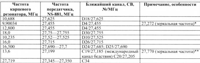
The second option for a similar use is an alarm button, which is constantly in the pocket of a truck driver - after all, they are the ones who most often use communication on the civilian range. This does not require special skills, permissions from Gossvyaznadzor, but only the registration of a radio station with a power of more than 1 W is necessary. If necessary, a truck driver can notify a colleague about an alarming situation. But you never know other practical applications of the NS-881; it's better than just "dusting" it in the bins. For myself, I made exactly a radio beacon connected to a motion sensor, which, using the contacts of the executive relay, supplies power to the transceiver. But in the process of work, two difficulties arose, which, however, are easily eliminated. The first difficulty: the selection of a frequency channel. First, the transceiver is "programmed" to transmit at 26,9 MHz. Neither the European frequency grid in the civilian range (the frequency channel ends at 5), nor the domestic one correspond to this frequency. The nearest channel is 1C on the European grid (26,965 MHz). European channels C2-C45, D1-D40 are officially approved for use in the Russian Federation. Even if you close the mode switch "on transmission" and install a jumper on the Morse code button (so that the sound generator constantly works), only a similar "toy" transceiver can receive the signal from such a radio beacon. And if it is not there or is notification required on a more common frequency? You will have to solder the quartz resonator and install another one instead, based on the information in the table. Since the vast majority of users have transceivers with a European frequency grid (even domestic TAIS transceivers are produced with it), it is reasonable to install a quartz resonator that best suits your "professional" transceiver, if one is available (for example, other models of portable radio stations : "Veda FM" - 27,1875 MHz, "Ural-R" - 27,175 MHz, "Pilot" - channels C38 and D5, corresponding to frequencies 27,385 and 27,465 MHz). There may be other options. After installing a new quartz resonator and fixing the "reception - transmission" mode switch, as well as installing a permanent jumper on the sound generation button, the modified NS-881 transceiver looks like in photo 2. Now, when power is supplied to the “toy”, which ceased to be such after refinement, we have a full-fledged radio beacon, which is very useful in the household for remote notification and warning the owners about certain events that occur at a distance of up to 1 km from home. The second difficulty is food savings. The "regular" power supply of the device - from the battery type "Krona" does not provide long-term operation of the newly made radio beacon. Therefore, if the situation allows, I recommend using a more powerful battery instead, for example, a D10-D12 with a capacity of 1,2 Ah and a voltage of 12 V. Such a voltage is not dangerous for the transceiver. To further reduce power consumption, I recommend replacing the standard bass amplifier with the one shown below. Correspondence of the frequency of the quartz resonator to the output frequency of the NS-881 transceiver
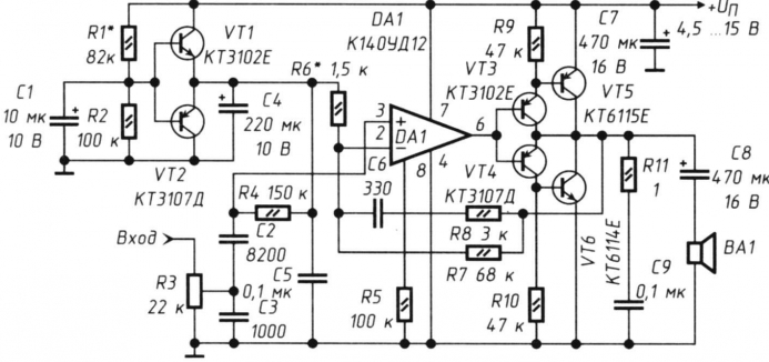
The fact is that in most developments of low-frequency amplifiers, transistors, K174XA10, K174UN4 microcircuits (and others) are used. As a result, even in the "calm" mode, in the absence of an input signal, the current consumption is quite large. The amplifier, the circuit of which is shown in the figure, has low distortion and a quiescent current of only 700 μA. Therefore, I recommend using it in the NS-881 (and in similar small-sized radio stations and radio receivers, in other devices where weak signal amplification is required in conjunction with economical power). The amplifier operates in the frequency range of 200 - 6000 Hz with a 3 dB unevenness. The output power at a supply voltage of 9 V is 0,3 W when operating on a load of VA1 with a resistance of 8 ohms. The circuit uses an economical micropower operational amplifier (op-amp) K140UD12. To amplify the low output current of the op-amp, a push-pull voltage follower with a high power gain (KUM) on four VT3-VT6 transistors is used. Circuit R11, C6 prevents self-excitation of the amplifier at high frequencies. The voltage gain (KUHN) is determined by the ratio of the resistances of the resistors R7 and R6. The cascade on transistors VT1 and VT2 serves to ensure the operation of the op-amp when powered from a unipolar source. The elimination of the conventional resistive amplifier avoids excitation of the amplifier at low frequencies. About details. The amplifier uses small-sized imported resistors with a dissipation power of 0,06 W. You can also use surface mount resistors. Oxide capacitors - K50-35, the rest - KT, KM-5, KM-6. As VT1, VTZ, transistors of the KT3102, KT3130, KG6111, KT342 series with any letter index are quite suitable. As UT2 and UT4 - any of the KT3107, KT6117 series. These transistors must have a base current transfer ratio of at least 200 mA. Instead of the VT5 transistor, any of the KT6115, KT6112, KT668, KT685 series is quite suitable. Transistor VT6 - KT6114, KT6117, KT645, KT680, KT683. The K140UD12 chip can be replaced with the KR140UD1208 (the pinout is the same). As a BA1, instead of a "regular" dynamic head from a portable CB radio station in the NS-881 range, I used 0,5-GDSh-2. Establishment. The volume control resistor R3 reduces the input signal level to zero. Further, by selecting the resistance R1, the voltage at the emitters VT1 and VT2 is set equal to half the supply voltage. By selecting the resistance R5, you need to set the quiescent current of the amplifier, equal to 700 μA. In this case, the engine of the variable resistor R3 should be in the lower (according to the diagram) position, and it is better to turn off the dynamic head for the time of measuring the current (to eliminate the error from the leakage current C7). The voltage gain is regulated by the selection of the resistance of the resistor R6.
It is advisable to check the finished amplifier using a generator and an oscilloscope. With the correct layout of the excitation elements, RF does not occur. Connection and application. The amplifier input is connected to the middle terminal of the variable resistor RP1 (designation on the board NS-881) of the radio volume control. The use of this amplifier in the NS-881 greatly increased battery life. An alternative to the described power amplifier can be an imported integrated ultrasonic frequency converter with a power consumption reduction mode. But such a mode cannot be used without a significant refinement of the detector of the radio receiving path, which makes the whole undertaking unprofitable in terms of time. Author: A.Kashkarov, St. Petersburg
Artificial leather for touch emulation
15.04.2024 Petgugu Global cat litter
15.04.2024 The attractiveness of caring men
14.04.2024
▪ Magnetic resonance imaging of a single atom ▪ The Earth and the Moon are formed from similar materials ▪ Teleportation of quantum logic ▪ Electronic cigarettes are not better than regular ones
▪ section of the site Factory technology at home. Article selection ▪ article Gait, like a boat in the sea. Popular expression ▪ article Where did the navy originate from? Detailed answer ▪ article Jamaican pepper. Legends, cultivation, methods of application ▪ article Multiband dipole. Encyclopedia of radio electronics and electrical engineering ▪ article Mobile phone car charger. Encyclopedia of radio electronics and electrical engineering
Home page | Library | Articles | Website map | Site Reviews
www.diagram.com.ua |


 Leave your comment on this article: