|
|


 Arabic
 Bengali
 Chinese
 English
 French
 German
 Hebrew
 Hindi
Hindi Italian
 Japanese
 Korean
 Malay
Malay Polish
 Portuguese
 Spanish
 Turkish
 Ukrainian
 Vietnamese
|
ENCYCLOPEDIA OF RADIO ELECTRONICS AND ELECTRICAL ENGINEERING VHF frequency synthesizer. Encyclopedia of radio electronics and electrical engineering
Encyclopedia of radio electronics and electrical engineering / Civil radio communications Recently, quite a few synthesizers for 144 MHz band equipment have appeared in print. The version of the synthesizer proposed in this article is interesting in that it uses an inexpensive LM7001J synthesizer chip used in household radio receivers. The synthesizer is designed to work in FM transceivers with an intermediate frequency of 10,7 MHz. It provides the formation of a signal with a frequency of 133,3 ... 135,3 MHz in the receive mode and 144 ... 146 MHz in the transmit mode with a frequency grid step of 25 kHz. It provides the ability to scan in receive mode over the entire operating frequency range. The synthesizer has a non-volatile memory for three user frequencies. It also contains 9 repeater channels (R0-R8). In the transmit mode, the synthesizer performs frequency modulation of the RF signal. The synthesizer is fed with a voltage of 8 ... 15 V. The consumption current is not more than 50 mA. The level of the high-frequency signal at its output at a load of 50 ohms is at least 0,1 V. Synthesizer operation When the supply voltage is applied, the synthesizer immediately starts working at the frequency recorded in the 1st memory cell. While the supply voltage is below 4,2 V, pin 1 (RES) of the DD1 microcontroller will have a logic zero level generated by the DA1 supervisor chip, which generates a reset signal. When this value is reached, the level will jump to "1". This eliminates the distortion of RAM information that occurs with a smooth increase in the supply voltage. The HG1 indicator shows the frequency at which the synthesizer will operate in transmit mode. To switch to the frequency recorded in one of the memory cells, you must press the corresponding button "1" - "3" (S1 - S3). Each press of the "UP" or "DN" button (S6 and S7) shifts the operating frequency up or down by 25 kHz, respectively. Pressing the "SCAN" button (S5) activates the scanning mode in the entire operating frequency range. When a carrier appears on the channel, scanning is suspended and resumes a few seconds after it disappears. The signal to stop scanning is the logic zero level applied to the "SCAN" output of the synthesizer. To exit the scanning mode, just press one of the "UP", "DN", "SCAN" buttons. When you press the "REP" (S4) button, the synthesizer switches to the mode of working with repeater channels. The transition through the channels is carried out with the "UP" and "DN" buttons. In this case, the indicator directly displays the channel number (R0 - R8). Scanning in repeater mode is not provided. This mode is exited by pressing the "REP" button again. To write the frequency to a memory cell, you must dial the frequency value on the indicator, press the button with the cell number and, without releasing it, press the "REP" button. When the power is turned off, the information recorded in the memory cells is retained. Operating principle The internal structure of the LM7001 chip, according to the documentation, allows you to build a frequency synthesizer for frequencies of 45 ... 130 MHz with a step of 25, 50 or 100 kHz. However, several copies of this microcircuit available to the author worked without problems at the amateur band frequencies of 2 meters. You can learn more about this chip from [3] or on the Internet at sites with technical information (for example, at [4]). The electrical circuit diagram of the synthesizer is shown in fig. one.
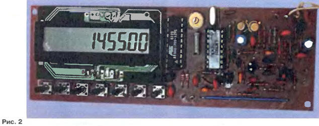
The synthesizer chip is controlled by the DD1 AT90S1200 microcontroller. This type of controller is chosen by the author as one of the cheapest on the market. Frequency indication is made with the help of LCD indicator used in imported telephones and caller IDs. The DD1 microcontroller, when the keys are pressed, processes commands, outputs data to the indicator and controls the operation of the DA2 synthesizer via a three-wire bus (pins 6, 7, 8 DD1). It is clocked from the internal DA2 oscillator operating at a frequency of 7,2 MHz. To transfer the synthesizer to the transmission mode, it is necessary to apply a zero logic level to the "TX" output of the synthesizer. The control voltage generator (VCO) is assembled on a VT3 transistor according to the "capacitive three-point" scheme. A VD5 varicap is used as a frequency tuning element. The VCO inductor consists of two parts. In receive mode, both parts of the coil "work", while transmitting - only one (large] part. Open drains of three keys (BO1 - WHO) on field-effect transistors that are part of the LM7001 microcircuit are connected to its outputs 7-9 The state of these keys changes when the corresponding control bits are changed. The microcircuit is programmed so that during reception, the key BO2 is closed, and the WHO is open. At the same time, the diode VD4 is closed and the coil L1 is fully turned on. When switching to the transmission mode, the key B02 opens, WHO closes, the diode opens VD4 and capacitance C7 grounds the alternating current of the smaller part of the coil.The buffer stage of the VCO signal is assembled on the transistor VT4. The composite cascade, assembled on transistors VT1 and VT2, acts as an inverting amplifier for the PLL error signal and an active filter. In transmit mode, the synthesizer signal is modulated in frequency by the speech signal applied to the "MOD" input of the synthesizer. The level of frequency deviation of the output signal depends on the amplitude of the speech signal. The amplitude of the speech signal must be such as to ensure the deviation of the output signal within the required limits. It is advisable to select its value already in the assembled radio station. The quality of the transmitted signal can be assessed using a closely spaced monitoring receiver. The supply voltage of the indicator HG1 (1,5 V) is removed from the divider R1VD1 - VD3. To match the levels of logical signals applied to the indicator, use resistive dividers R2 - R5. Construction and details The entire structure is assembled on a single printed circuit board with dimensions of 148x50 mm, made of one-sided textolite (Fig. 2).
The drawing of its trace is shown in fig. 3, and the arrangement of elements - in fig. 4
The design used constant capacitors type K10-17 or KM. Trimmer capacitor C3 - type KT4-23. Electrolytic capacitors C14 and C15 - type K50-35. Fixed resistors - type C2-23, C1-4. To rebuild the VCO, the author used the KV134AT-9 varicaps available to him. Instead, you can successfully use any high-frequency low-voltage varicaps with an initial capacitance of 18-22 pF. The DA1 supervisor chip can be replaced with an imported analog PST529D. A ten-digit LCD module with an HT1611 controller from Holtek was used as an indicator. The inductor L1 has 0,5 and 2,5 turns (counting from the "cold" end) with a 0,45 mm wire on a 4 mm mandrel. Choke L2 is wound on resistor R24 and contains 15 turns of wire with a diameter of 0,15 mm. Setting After assembling the synthesizer, it is necessary to unsolder the upper (according to the diagram) output of the resistor R17 and apply a voltage of +2,5 V to it from an external source. Turning on the synthesizer, it is transferred to the transmission mode and the frequency of the VCO is measured at the "OUT" output using a frequency meter. By shifting and pushing the turns of most of the inductor L1, they ensure that the frequency of the generated signal is as close as possible to the value of 145,5 MHz. After that, the synthesizer is switched to receive mode and the frequency value is again controlled. By changing the shape of the smaller part of the coil, the frequency generated by the VCO is set to be close to 134,8 MHz. At the end of the VCO frequency adjustment, the coil turns are fixed with paraffin or wax, the output of the resistor R17 is soldered to the board. Next, a frequency meter is connected to the output of the synthesizer. Adjusting C3 ensures that the frequency of the generated signal on any channel differs from the required one by no more than a few hundred hertz. The final stage is to check the operation of the synthesizer in all modes. The control voltage on the varicap in the operating frequency range should be within 1,5 ... 4,5 V. Microcontroller programming To program the AT90S1200, the author used the RopuRgod2000 programmer developed by Claudio Lanconelli. The latest software releases, programmer diagrams for various types of microcontrollers and detailed instructions for use can be found in [5], and useful information on using the programmer can be found in [1]. The programmer contains a base unit connected to the COM or LPT port of the computer, and replaceable adapters for each family of microcontrollers. However, if you plan to program only a certain type of microcircuit, for example, AT90S1200 and AT90S2313, then you can use a simplified adapter for the COM port (Fig. 5).
Data for programming the microcontroller and RAM Using the synthesizer During the operation of the synthesizer, in order to reduce parasitic pickups that reduce the signal quality, it must be placed in a shielded compartment. The design proposed by the author (the location of the microcontroller, synthesizer chip and VCO on the same board) is not always convenient. If necessary, you can place the synthesizer chip and VCO on a separate board, and also use a different VCO circuit. It is not necessary to change the microcontroller firmware program. Literature
Author: A. Temerev (UR5VUL), Svetlovodsk, Ukraine
Artificial leather for touch emulation
15.04.2024 Petgugu Global cat litter
15.04.2024 The attractiveness of caring men
14.04.2024
▪ Smart surveillance camera with tracking function ▪ Acnodes PCM8019 Rugged Embedded Computer ▪ Kamchatka deer were microchipped
▪ Telephony site section. Article selection ▪ article Hidden loop. Tips for the home master ▪ article What is dodecaphony in music? Detailed answer ▪ article General information about the human body and its interaction with the environment
Home page | Library | Articles | Website map | Site Reviews
www.diagram.com.ua |


 Leave your comment on this article: