|
|


 Arabic
 Bengali
 Chinese
 English
 French
 German
 Hebrew
 Hindi
Hindi Italian
 Japanese
 Korean
 Malay
Malay Polish
 Portuguese
 Spanish
 Turkish
 Ukrainian
 Vietnamese
|
ENCYCLOPEDIA OF RADIO ELECTRONICS AND ELECTRICAL ENGINEERING Modern KB range power amplifier. Encyclopedia of radio electronics and electrical engineering
Encyclopedia of radio electronics and electrical engineering / Civil radio communications Power amplifiers for the short wave band are a fairly conservative area of technology. It is not always possible for a radio amateur to immediately make a high-quality device that would meet all the requirements. Lack of experience and lack of necessary funds can also affect here. To facilitate the process of designing, manufacturing and further modernization of the amplifier, it would be advisable to apply the principle of open architecture, once laid down by IBM in computers. A principle that allows you to assemble any given configuration in a universal case of the system unit and, as necessary, replace individual nodes with more advanced ones, reducing rework and costs to a minimum. A modern KB range power amplifier can be divided into functional blocks, which are advisable to be manufactured as separate units and installed in a universal housing in a given combination (configuration), according to user requirements, for example:
As a universal case, the "Mini-Tower" case, from the computer system unit, is most suitable. Such a case, in comparison with the traditional horizontal one, has a number of advantages:
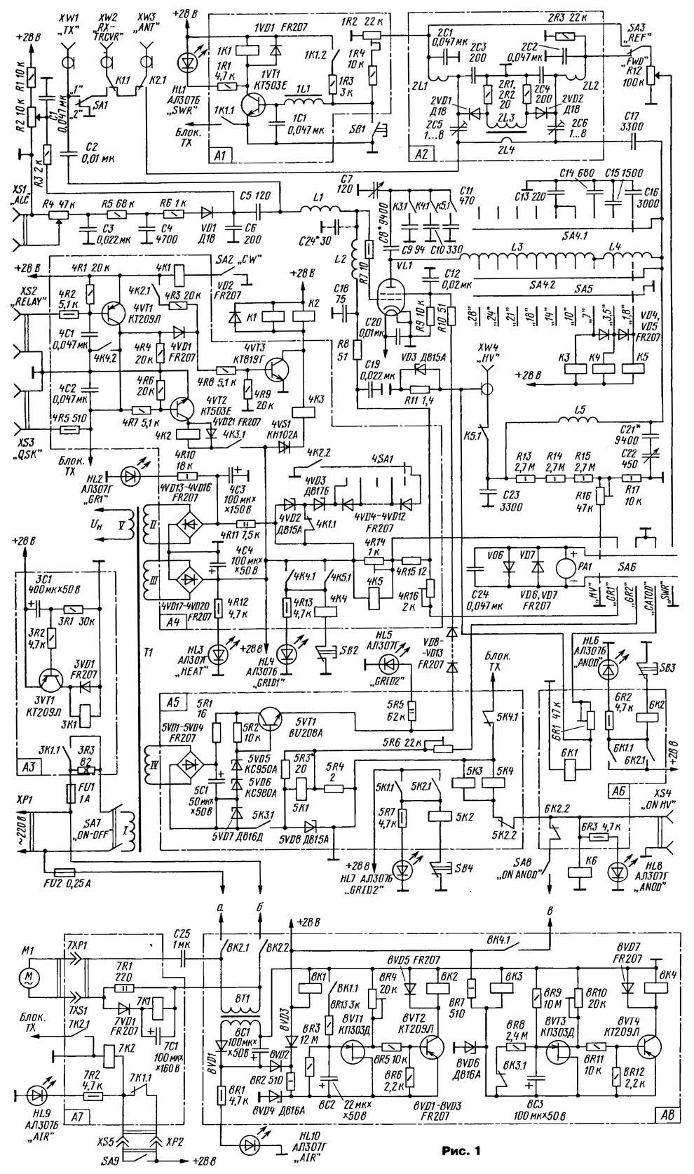
In the "Mini-Tower" case, two options for the design of the amplifier are possible. The first - with an internal anode power supply. This arrangement is suitable for an amplifier with four GU-50 lamps (2 GU-72, 2 GMI-11,2 GI-7B, 2 GK-71, GU-74B) with a power transformer of 600. ..800 W. It is also suitable for more powerful lamps, provided that the anode voltage is obtained using a multiplier. The second option, with an external anode power supply, is designed for lamps GU-43B, GU-84B, GU-78B, GS-35B, GU-81M. This arrangement is more versatile, since the external anode power supply can be upgraded without affecting the main design of the amplifier. The principle of open architecture was used in the design of the amplifier, the schematic diagram of which is shown in fig. 1. The amplifier is made on a GU-78B (VL1) lamp, connected according to the common cathode circuit, and provides a gain of at least 15 dB on all nine amateur bands.
In all parameters and a set of service functions, the amplifier corresponds to the world level. Its dimensions, excluding protruding parts, are 330x178x390 mm, weight - 17,5 kg. The amplifier has five independent safety systems. They protect the lamp from exceeding the current of the grids and the anode, from overheating when the fan stops and when the P-circuit is detuned, and also turn off the amplifier at high SWR values. The automation of the amplifier provides a step-by-step switching on of the lamp incandescence, a four-minute warm-up of the lamp before applying the anode voltage and a five-minute cooling of the lamp after the heating voltage is turned off. Due to the use of an external anode power supply and a vertical case, it was possible to fit into the dimensions of the "Mini-Tower" computer case without prejudice to the installation. Sockets XW1, XW2, XW3 are intended for connection with the transceiver and antenna. When using a common transceiver antenna and a transceiver with one "ANT" connector, they are connected to the XW3 and XW2 sockets, respectively. Connector XW1 is not used and switch SA1 is in position "1". If the transceiver has separate connectors for "RX and "TX" antennas, the amplifier also allows you to use a separate antenna for reception. To do this, switch SA1 is switched to position "2"; the output "TX" of the transceiver is connected to the socket XW1, and the input of the transceiver "RX" - with a receiving antenna. It should be noted that, using separate "RX" and "TX" connectors in the transceiver, if SA1 is accidentally transferred to position "1", all its output power will go to the receiver input. Therefore, the switch SA1 has a latch, protection against accidental switching. When transmitting a signal from the transceiver through the capacitor C2, the elements of the low-pass filter L1, C5, C6, C24 and the resistor R7 are fed to the control grid of the lamp VL1. A fifth-order low-pass filter and resistor R8 provide an input impedance of 50 ohms on all ranges. The amplifier uses a series power supply circuit for the lamp control grid, which does not require the use of a choke. The bias voltage is applied to the point of the circuit with zero RF potential, to the lower output of the resistor R8 according to the circuit. At the same time, the negative voltage circuit does not affect the operation of the lamp at high frequency, which increases the stability of the amplifier. A P-circuit is connected to the anode circuit of the VL1 lamp, made according to the serial power scheme, through the L5 choke. It includes coils L3 L4, tuning capacitors C7, C9-C11 and capacitors for adjusting the connection with the antenna C13-C16, C22. Isolating capacitors C8, C17, C21 prevent the high anode voltage, under which the P-circuit is located, from entering the KPE C7, C22 and the antenna. In the P-circuit, a KPI with a small maximum capacitance is used, to which on the ranges of 1,8; 3,5 and 7 MHz additional constant capacitors are connected. This option reduces the dimensions of the KPI and the P-circuit as a whole and significantly reduces the sharpness of tuning at frequencies of 14 ... 28 MHz due to the "electric vernier", making it more convenient to change the range. Capacitor C7 is connected to the anode KPE C7 in the range of 9 MHz by a short circuit. On the 3,5 MHz range, the capacitor C4 is additionally connected with the K9 contactor in parallel with C10. And on the 1,8 MHz range, the K5 contactor, in parallel with them, connects the capacitor C11. Serial connection of KZ-K5 is provided by the SA5 switch through diodes VD4, VD5. Switching ranges in professional and branded power amplifiers, as a rule, is carried out by mechanical switches, since they are the most structurally simple and reliable. This design also uses the SA4 mechanical switch developed by the author [3]. Its contact group SA4.2 switches the taps of the L3 coil, and the SA4.1 contact group connects permanent capacitors C12-C16 in parallel to the C22 antenna KPE. The axis of the switch SA4 through the insulator is rigidly connected to the axis of the switch SA5. The SA5 switch is installed on the front panel of the amplifier; it controls the KZ-K5 contactors. To fix the positions of the switch SA4, the lock of the switch SA5 is used. Although the dimensions of the P-circuit compartment make it possible to make the switch completely on vacuum contactors (and they will need 13 pieces), this option is many times smaller than them in size, cheaper, simpler and more reliable. Anode voltage from an external anode power supply is supplied to socket XW4 ("HV") via coaxial cable PK 50-7-15. Resistors R13-R15, R17 - measuring voltage divider. The trimming resistor R16 sets the total deviation of the arrow of the RA1 device at a voltage of 4 kV. Turning on the fan, lamp glow, bias voltage, anode and screen voltages is controlled by green LEDs HL10 ("AIR"), HL3 ("HEAT"), HL2 ("GR1"), HL8 ("ANOD") and HL5 ("GRID2") . The PA1 device allows you to control the value of the anode voltage ("HV"), grid currents ("GR1" and "GR2"), cathode current ("CATOD") and SWR ("SWR"). The ALC control voltage is obtained by rectifying a portion of the transceiver's RF input voltage. This allows you to set the gain level without the lamp control grid current and can be used for any type of lamps connected in a common grid or common cathode circuit. At low input signal levels, the diode VD1 is closed by a positive voltage supplied to it through resistors R1, R2, R3. There is no ALC control voltage. The variable resistor R2 sets the threshold for opening the VD1 diode and the appearance of the ALC control voltage at the XS1 socket. Variable resistor R4 regulate the level of this voltage. The amplifier is turned on with the SA7 toggle switch. At the same time, filament and negative voltages are supplied to the lamp from the power sources, and a voltage of +28 V is supplied to the automation circuits.
The A1 board has a circuit for protecting the amplifier from high SWR values. The reflected wave voltage coming from the SWR meter board opens the 1VT1 transistor. Relay 1K1 turns on and its contacts 1K1.1 blocks the TX transmission mode. At the same time, the 1K1.2 contacts through the 1R3 resistor supply a positive voltage to the 1VT1 base, keeping it open after the TX mode is turned off. The protection operation is signaled by the red LED HL1 ("SWR"). The circuit returns to its original state by pressing the SB1 button. The level of the reflected wave at which the protection circuit is triggered is set by the 1R2 trimmer. On board A2 is a SWR meter. It is made according to the traditional scheme and does not require explanation. Board A3 - the timer of the stepped voltage supply of the glow. To limit the inrush current, a 1R3 resistor is included in the primary circuit of the transformer T3. When the amplifier is turned on and a voltage of +28 V is applied through the resistor 3R1, the capacitor ZC1 begins to charge. After 5 s, the 3VT1 transistor opens and the ZK1 relay turns on, which short-circuits the 1.1R3 resistor with its contacts ZK3, providing full voltage supply. The delay time depends on the values of 1C3 and 1R3. Resistor 2R1 prevents shunting of capacitor ZCXNUMX by the low input resistance of the transistor. On board A4, on diodes 4VD13-4VD16 and capacitor 4C3, a power supply for the bias circuit of the first grid of the lamp (-100 V) with current protection, an RX / TX mode switch and a voltage source of + 28 V (4VD17-4VD20,4С4) are made. To control the amplifier from any proprietary transceiver, the XS2 ("RELAY") jack is used. When its contacts are closed to a common wire (TX mode), the 4VT1 transistor opens and the positive voltage across the 4R4 resistor opens the 4VT3 transistor. Antenna relays K1 and K2 are switched on. With some delay, determined by the dinistor 4VS1, the 4KZ relay is turned on, and then 4K2. Contacts 4K2.2 include a source of -100 V, and the lamp opens. Relay 4K2.1 contacts hold the 4VT3 transistor in the open state. The 4VD1 diode prevents the simultaneous blocking of the 4VT2 transistor. When switching to the RX mode, the 4K2 relay will first turn off and “close the lamp” with its 4K2.2 contacts, and then, after opening the 4K2.1 contacts, the antenna relays will switch. To control the amplifier from a homemade transceiver, type RA3AO, the XS3 ("QSK") socket is used. The control voltage of the transceiver (+12 V) is immediately supplied to the 4R4 resistor, and then the circuit operates according to the above cycle. If a homemade transceiver does not have a special control voltage output, it can be taken, for example, from the antenna relay winding. The 4SA1 switch and 4VD3-4VD12 diodes allow you to accurately set the operating bias voltage on the first grid of the lamp. To reduce the quiescent current of the amplifier in CW mode. using relay contacts 4K1.1 connects an additional zener diode 4VD2. This mode is activated by the SA2 toggle switch. When the current of the first grid is exceeded, the control relay 4K5 is activated and with its contacts 4K5.1 it turns on the relay 4K4, which blocks the transmission mode with its contacts 4K4.2 and closes the lamp. At the same time, through contacts 4K4.1, voltage is applied to the relay 4K4, keeping it on. The red LED HL4 ("GRID1") signals the activation of the protection. The protection circuit returns to its original state by pressing the SB2 button. The protection operation current is regulated by a trimming resistor 4R14. Resistor 4R15 - circuit for measuring the current of the first grid. The trimming resistor 4R16 sets the total deviation of the arrow of the PA1 device at a current of 15 mA. On the A5 board, a screen voltage source is assembled. It includes a rectifier (5VD1-5VD4, 5C1), a stabilizer (5VT1, 5VD5-5VD8) and a relay circuit for protecting the second grid from overcurrent. The screen voltage source also includes resistors R9, R10 and diodes VD8-VD13. In the event of an emergency shutdown in the anode voltage transmission mode, the current of the second grid increases significantly and the permissible power dissipated on it is exceeded. At a second grid current of 100 mA, the 5K1 relay is turned on and with its 5K1.1 contacts it turns on the 5K2 blocking relay. which, in turn, switches off the 5KZ and 2.2K5 relays with contacts 5K4. Contacts 5KZ. 1, the screen voltage is turned off, the 5K4 relay blocks the TX mode, while the 5K2.1 blocking contacts supply voltage to the 5K2 relay, keeping it on. The red LED HL5 ("GRID2") signals the activation of the protection. The protection circuit returns to its original state by pressing the SB4 button. The protection operation current is set by the 5R3 resistor. Since a current of 9 mA constantly flows through the resistors R5 and 3R40, then for the protection to operate at a grid current of 100 mA, the 5K1 relay must turn on at a current of 140 mA. Resistor 5R4 is used to measure the screen grid current. The trimming resistor 5R6 sets the total deviation of the arrow of the PA1 device at a current of 150 mA. In addition to relay protection, the A5 source has four safety elements that ensure its safety when the second grid is closed to the cathode or anode due to a malfunction or breakdown of the lamp. Resistors 5R1, R10 limit the maximum short-circuit current in the period before the protection trips. The 5VD8 zener diode limits the current passing through the 5K1 low-current relay and 5R3 and 5R4 resistors in the period before the protection trips. Diodes VD8-VD13 provide source protection in the event of a dynatron effect and when the grid is shorted to the anode. Also, the resistor R9 provides neutralization of the dynatron effect. The anode current protection circuit is located on the A6 board. At a current of 1,8 A, the control relay 11K6 connected in parallel with the resistor R1 is turned on. The operation of the blocking relay 6K2 and the shutdown relay Kb occurs as in the previous circuit. At the same time as the anode voltage is turned off, the 6K2.2 contacts also turn off the screen voltage. The activation of the protection is indicated by the glow of the red LED HL6 ("ANOD"). The circuit breaker is transferred to the initial state by pressing the button SB3. The zener diode VD3 protects the 6K1 relay and the R11 resistor from a short circuit current for a while before the protection trips. Resistor R11 also serves to measure the cathode current. A tuned resistor 6R1 sets the total deviation of the arrow of the device RA1 at a current of 2A. Relays for switching on screen (K6) and anode (5KZ) voltages, in addition to protection functions, are also used when the warm-up timer is running and for manually turning off these voltages with the SA8 switch during adjustment work. The A7 board contains a circuit for protecting the VL1 lamp from overheating, which is possible when the fan stops and with increased heat generation at the anode. An open in the motor circuit causes the 7K1 relay to turn off. Its 7K1.1 contacts close and turn on the 7K2 relay, which blocks the transmission with its 7K2.1 contacts. The protection operation is signaled by the red LED HL9 ("AIR"). After the break is eliminated, the protection circuit returns to its original state. In the event of a short circuit in the motor circuit, the FU2 fuse blows and the protection circuit operates as if it were open. To protect the lamp from overheating when the P-circuit is detuned, the SA9 temperature sensor (contact thermometer) is used, which is located in the air duct above the lamp. The temperature sensor controls the temperature of the air behind the anode, since the anode of the lamp is under high voltage. When the air temperature exceeds, corresponding to the maximum allowable temperature of the anode, the contacts of the thermal sensor close and turn on the relay 7K2, which blocks the transmission with contacts 7K2.1. The activation of the protection is signaled by the red LED HL9 ("AIR") After the protection is activated, the contacts of the temperature sensor SA9 remain closed for some time, while the heat is removed from the anode of the lamp, and then the protection circuit returns to its original state. The anode and screen voltages are supplied to the lamp by turning on the SA8 toggle switch through the warm-up timer, which is structurally combined with the cooling timer on the A8 board. When operating the amplifier with a warm-up timer, the SA8 toggle switch is permanently on. It can be used to turn off high voltage during adjustment and repair work. In addition, when the screen voltage is removed, the TX mode is simultaneously blocked, which allows you to quickly turn off the amplifier during local QSOs, while keeping it, as they say, "under steam". When a voltage of +28 V appears, the 8KZ 1 contacts open and the 8C3 capacitor begins to charge. The voltage at the source of the 8VT3 transistor rises, and after 4 minutes the 8VT4 transistor opens, including the 8K4 relay. Through the 8K4 1 contacts, the +28 V voltage will go to the SA8 switch and to the XS4 connector, through which the external anode power supply is switched on remotely. The lamp warm-up time is set by 8R7 and 8C3. Resistor 8R6 determines the delay in the supply of anode and screen voltages when the amplifier is turned on again. At the same time, +28 V is supplied through the 8VD3 diode to the cooling timer, which controls the operation of the fan. Closed contacts 8K1.1 supply voltage to the gate of the transistor 8VT1. After the 8C2 capacitor is quickly charged, the voltage at the 8VT1 source opens the 8VT2 transistor and the 8K2 relay is activated, which connects the M8 fan motor and the 2T1 transformer of the cooling timer power supply to the network with contacts 8K2.2 1 and 8K1. The electric motor Ml is powered by a reduced voltage through the capacitor C25. During the operation of the amplifier, the cooling timer is powered from the +28 V circuit, and the diodes 8VD2 and 8VD3 provide decoupling between two sources with different voltages. After the amplifier is turned off, the contacts 8K1 open and the capacitor 8C2 begins to discharge through the resistance 8R3. Now the timer is powered from a +20 V source on the 8T1 8VD1, 8C1 elements, and the 8VD3 diode does not pass this voltage to the relay and automation circuits. 5 minutes after the start of the discharge of the 8C2 capacitor, the voltage at the 8VT1 source becomes insufficient to keep 8VT2 open, the 8K2 relay turns off and its contacts open the 220 V circuit that feeds the fan and the cooling timer. The operating time of the cooling timer depends on the values of 8R2 and 8C2 Trimmer resistors 8R4 and 8R10 set the closed state of transistors 8VT2 and 8VT4 with discharged capacitors 8C2 and 8C3. To protect the field-effect transistors 8VT1 and 8VT3 from RF interference, their outputs must be connected to a common wire through 0,047 uF capacitors. To simplify the circuit in fig. 1 they are not shown. The diagram of an external anode power supply is shown in fig. 2. When the SA2 switch is open, relay K1 provides remote control of the power supply. The +28 V voltage supplied to the XS2 sockets from the power amplifier turns on this relay, and through its K1.1 contacts, the mains voltage will be supplied to the transformers T1 and T2. In the absence of a control voltage of +28 V, switching on can be done by switch SA2.
The high voltage source has six short circuit protection elements. Three of them are located in the high voltage circuit and three in the 220 V circuit. A relay circuit breaker located in the amplifier case (A6 board in Fig. 1) protects against excess current in the anode circuit. If the relay protection fails or if a short circuit occurs in the circuits located before it, the fuse FU2 is activated. Resistor R2 reduces the short-circuit current in the period before the protection trips. The SA220 circuit breaker is included in the 1 V power circuit, which protects against overcurrent in the primary windings of transformers. The stepping resistor R1 limits the starting current. It protects the diodes at the moment of switching on in case of a short circuit in a high-voltage circuit and when charging capacitors. The turn-on delay occurs due to the response time of relay K2. The fuse FU2 protects the resistor R1 from thermal destruction during a high voltage short circuit at the moment of switching on, when the capacitors are not yet charged. Different protection elements in the low and high voltage circuits are necessary, since the short circuit mode at the time of switching on and during operation occurs in different ways. With charged filter capacitors in short circuit mode, the rectifier can be considered as two voltage sources operating on the same load. One of them with low internal resistance is capacitors, and the other with high internal resistance is a rectifier. Therefore, with charged capacitors in short circuit mode, the vast majority of the current in the load is provided by capacitors, not diodes. The operation of the relay K6 (see Fig. 1) or the fuse FU2 (Fig. 2) occurs due to the energy stored in the capacitors. The current through the rectifier diodes and in the 220 V circuit simply does not have time to increase before the protection is triggered. Therefore, the protection elements in the 220 V circuit do not work in this case. In the event of a short circuit at the moment of switching on due to uncharged capacitors, the entire load falls on the rectifier. This causes a sharp increase in current in the 220 V circuit and a large voltage drop across the resistor R1 Therefore, relay K2 will not be able to turn on and short R1 and FU1. In this case, the fuse FU1 protects the resistor R1 and the short circuit drain rectifier diodes. On fig. 2 diode bridges VD1, VD2 and smoothing capacitors C1, C2 are shown in a simplified way. In each arm of the rectifier bridges VD1 and VD2, four and two KD202R diodes, respectively, are connected. Each diode is shunted with a MLT-0,5 470 kOhm resistor. Each of the capacitors C1 and C2 is made up of ten oxide capacitors with a capacity of 220 microfarads x 400 V, shunted with MLT-2 100 kOhm resistors. The winding data of the main inductors of the amplifier are given in Table. 1. Choke 1L1 - standard D-0,1 50 μH. Chokes 2L1, 2L2 - D-0,1 500 μH.
The power transformer of the power amplifier T1 is wound on a toroidal magnetic circuit with a size of 92x60x60 mm made of E3413 electrical steel. Its winding data are given in Table. 2.
Transformer 8T1 with a power of 2 W has a voltage on the secondary winding of 18 V. Transformers T1 and T2 in the external anode power supply have an alternating voltage on the secondary winding of 1600 and 750 V, respectively. External anode power supply dimensions - 255x380x245 mm, weight - 22 kg The amplifier uses fixed resistors - MLT, tuning - SP4-1. Resistor R10 is made up of ten two-watt resistors C3-13 of 510 ohms, connected in parallel. Resistor R9 is made up of ten MLT-2 resistors of 100 kOhm each. Resistor R11 is made up of three 1 ohm MLT-4,3 resistors. Capacitors C9 and C10 are composed, respectively, of two and seven capacitors K15-U1 47 pF per 13 kvar. Capacitor C11 - K15-U1 for 40 kvar. Capacitors C13-C16 - K15-U2 or KVI-3. Capacitors C8, C21 are made up of two capacitors KVI-3 4700 pFx5 kV. C17 and C23 - KVI-3 3300 pfx10 kV. The air gap between the stator and rotor plates for C7 is 3 mm, for the capacitor C22 it is 1,3 mm. All oxide capacitors are from SAMSUNG, the rest are KSO. KD, KTP. Relays K1 and K2 - GUID. Relay KZ-Kb - vacuum contactors V1V. Parallel to the windings of the K1-Kb relay, blocking capacitors with a capacity of 0,047 μF are connected (not shown in Fig. 3). Relay 1K1, 4K2, 5K2, 6K2 - RES60 (version RS4.569.435-00). Relay ZK1, 5KZ, 8K2 - RES9 (RS4.529.029-00). Relay 4KZ - RES91 (RS4.500.560). Relay 4K1, 5K4, 7K2, 8K1, 8KZ, 8K4 - RES49 (RS4.569.421-00). Relay 5K1 and 6K1 - RES49 (RS4.569.421-03). Relay 7K1 - RES-55A (RS4.569.600-02). In the external anode power supply unit, the AC relay K2 - RP-21 for 220 V, the relay K1 - TKE53PD for a voltage of 27 V. Device RA1 - M4205 With a total deflection current of 100 μA. Its scale for reading SWR, lamp currents and voltages is made on a computer, covered with plastic and glued to the main metal scale. The appearance of the amplifier is shown in the photo. Its internal layout is shown in Fig. 3. The case consists of front and rear panels, which are connected from below by the bottom, and from above on the sides - by corners. At the rear of the case, an L-shaped partition separates the inlet compartment. It contains input circuits, an ALC voltage generation circuit, resistors R9, R10, diodes VD8-VD13 and a ventilation unit. Also in the compartment are printed circuit boards A6-A8.
The amplifier uses a forced-air lamp cooling system with a centrifugal fan. The fan case is docked to the lamp panel. The fan electric motor is attached to the bottom of the housing using an L-shaped bracket and vibration isolators. The fan impeller is fixed on the motor shaft KD-6-4-U4 (n = 1400 rpm). Impeller diameter - 92, width - 30 mm. The use of a centrifugal fan and an electric motor with porous bronze bearings operating at reduced voltage made it possible to minimize the noise level and make it less than in a computer system unit. The cooling system ensures the operation of the transmission amplifier at a power of 950 W dissipated on the GU-78B anode for an unlimited time. This makes it possible to work even in mode A with partial output power. In modes AB, and B, (when working in CONTEST), the ventilation unit provides a double supply of air supply. Above the input compartment, on the side of the lamp, there are relays K6 and elements of the anode power circuit. An air duct is located above the lamp panel to remove heat outside the housing. It contains a temperature sensor for thermal protection of the lamp. The front part of the case is divided by a horizontal partition into two compartments. Above are the P-circuit and the range switch. Their parts are fixed on a longitudinal vertical baffle, which connects the front panel with a horizontal baffle and enhances the rigidity of the case. Under the horizontal partition there is a transformer T1 and printed circuit boards A1, A3-A5. A false panel with inscriptions is fixed on the front panel. On the rear panel are all connectors, ALC R2, R4 regulators and fuses FU1, FU2. In its upper part there is an SWR meter board and antenna relays K1 and K2. This arrangement allows, if necessary, to easily upgrade the antenna switch and install any available relays without affecting the main structure. The relay and the SWR meter are covered by a common casing. In the upper plane of the casing, opposite the lamp panel, a hole with a diameter of 126 mm is cut out for heat to escape. It is covered with a metal mesh with 5x5 mm cells and allows you to measure the temperature of the lamp with a thermocouple when the casing is closed. On the sides of the casing, opposite the ventilation unit, two air intake openings with dimensions of 100x130 mm are cut out. They are covered with a metal mesh with 3x3 mm cells. For blowing lamps, the design of a vertical housing with a supply cooling system from a centrifugal fan is optimal. This, figuratively speaking, is the "motherboard" of a linear amplifier, which remains unchanged during modernization. Most of the amplifier circuit is assembled on printed circuit boards, each of which is a complete functional unit. All printed circuit boards, except A3, are mounted on rotating brackets that provide easy access for adjustment, diagnosis and repair. As new electronic components become available and proliferate, this design will allow the amplifier to be upgraded in stages. For example, make non-contact self-unlocking current protection, automatic digital SWR meter, digital high SWR protection circuit, digital timers, etc. In the amplifier without significant alterations, a GU-84B lamp can be used. Internal power supplies and ventilation installation are designed for both lamps. The equivalent resistance of these lamps differs slightly, therefore, to switch to GU-84B, it is necessary to select the bias voltage, as well as replace the lamp anode ring and the external anode power supply. To operate the GU-84B in nominal mode, it is recommended to increase the screen voltage from 330 to 375 V by removing the jumper from the 5VD7 zener diode. The author is grateful to I. Loginov (UA1XN), A. Matrunich (EU1AU) and V. Romanov (RZ3BA) for their help in the manufacture of the amplifier. Literature
Author: Vitaly Klyarovsky (RA1WT), Velikie Luki
Artificial leather for touch emulation
15.04.2024 Petgugu Global cat litter
15.04.2024 The attractiveness of caring men
14.04.2024
▪ Diamond stretching for microelectronics ▪ Connecting a car to a smart home ▪ Quantum computers for data processing ▪ Which book is more environmentally friendly ▪ Electronic system for simultaneous interpretation into the sign language of the deaf and dumb
▪ section of the site Videotechnique. Article selection ▪ article Knight for an hour. Popular expression ▪ article Where did grapefruits originate? Detailed answer ▪ article Deren Siberian. Legends, cultivation, methods of application
Comments on the article: Jury Useful article.
Home page | Library | Articles | Website map | Site Reviews
www.diagram.com.ua |


 Leave your comment on this article: