|
|
ENCYCLOPEDIA OF RADIO ELECTRONICS AND ELECTRICAL ENGINEERING VOX for FT-840M. Encyclopedia of radio electronics and electrical engineering
Encyclopedia of radio electronics and electrical engineering / Civil radio communications In some low-priced imported KB radio amateur transceivers, which include the FT-840 from YAESU, there is no voice control system for transmitting and receiving mode switching (VOX), and there is also no manual IF gain control. In my FT-840 transceiver a few years ago I installed a VOX, the circuit of which is shown in fig. 1. As a delay element, a single vibrator based on an integral timer 1006VI1 is used. The scheme is quite simple and does not require explanation.
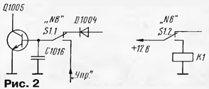
VOX is hinged on a small breadboard, which is installed inside the transceiver case on the rear wall ventilation grille. Adjusted resistors - SPZ-19a, oxide capacitors - K53-1, relay - RES55A (passport RS4.569.604). The input of the device is connected with a shielded wire to the microphone input of the MAIN-UNIT board of the transceiver - connector J1014. Relay contacts K1.1 are connected in parallel with the RTG socket (J1024 connector). Power to the VOX can be taken from the J1020 connector (pin 4). Establishing VOX comes down to setting the trimmer resistor R1 to the signal level from the microphone, at which the relay is activated and the transceiver switches to transmission. The tuning resistor R5 sets the VOX turn-off delay time (0,5 ... 1 s). Manual IF gain control is the main one used by the operator when listening to the air. Its absence in some cases creates an overload of the transceiver's receiving path with powerful signals and, as a result, distorted unintelligible reception. In order not to install additional knobs and switches in my transceiver, I decided to use the existing, but not used when working on the KB, the "SQL" squelch control potentiometer and the "NB" button. An additional relay is installed in the transceiver to retain the functions of this control when working with FM. The alteration scheme is shown in fig. 2 and 3. The "NB" S9204 surge suppressor switch "NB" S1 was used as the "ARC-RRU" switch. The printed conductors connecting it to the elements of the transceiver are cut, and the switch (designated as S2) is connected to the transceiver circuit by surface mounting, as shown in fig. XNUMX.
Relay K1 - RES22 (passport RF4.500.129). The +12V supply can be taken from pin 2 of J1020. In order for the transceiver's surge suppressor to remain permanently on, pin 5 of J1011 should be connected to ground. The tracks connecting the VR7201-1 potentiometer to the JP7201 connector are cut. The outputs of the potentiometer are connected by hanging wires to the contacts of relay K1, as shown in fig. 3.
Resistors R1-R3 are also mounted in a hinged way. Wire "A" is the green regular wire previously connected to the "SQL" regulator. Wire "Control" goes to the base of transistor Q1005 of the AGC amplifier of the transceiver through switch S1 (see Fig. 2). +9V power can be taken from pin 4 of connector J1007 on the MAIN-UNIT board of the transceiver. After the alteration, in the non-pressed state of the "NB" key, the AGC of the transceiver works, and the "SQL" regulator is used for its intended purpose. When the "NB" key is pressed, the "SQL" knob performs the function of manually adjusting the IF gain. It should be noted that the IF gain adjustment is "reverse", i.e. when the potentiometer axis is turned clockwise, the gain of the IF path decreases. I don't think it matters. Author: N. Shadrin (RZ4HX)
A New Way to Control and Manipulate Optical Signals
05.05.2024 Primium Seneca keyboard
05.05.2024 The world's tallest astronomical observatory opened
04.05.2024
▪ LDB - DC-DC Buck-Boost LED Driver Series ▪ Laser turrets for combat aircraft ▪ The robot will determine the salinity of the dish ▪ Gut microflora affects our health and mood ▪ Qualitative growth of semiconductor lasers on silicon
▪ section of the site The most important scientific discoveries. Article selection ▪ article by Alexander Humboldt. Famous aphorisms ▪ article What were the first means of transportation? Detailed answer ▪ Manicurist article. Job description ▪ article Soldering iron power regulator. Encyclopedia of radio electronics and electrical engineering ▪ article Low battery indicator. Encyclopedia of radio electronics and electrical engineering
Comments on the article: Sergei I soldered the circuit correctly, but I can't get it to work. Where can be "podlyanka"? Kazbek The value of the resistor R3 in one figure is 470 kOhm, in the other figure it is 470 Ohm. Who to believe?
Home page | Library | Articles | Website map | Site Reviews www.diagram.com.ua |


 Arabic
 Bengali
 Chinese
 English
 French
 German
 Hebrew
 Hindi
Hindi Italian
 Japanese
 Korean
 Malay
Malay Polish
 Portuguese
 Spanish
 Turkish
 Ukrainian
 Vietnamese


 Leave your comment on this article: