|
|


 Arabic
 Bengali
 Chinese
 English
 French
 German
 Hebrew
 Hindi
Hindi Italian
 Japanese
 Korean
 Malay
Malay Polish
 Portuguese
 Spanish
 Turkish
 Ukrainian
 Vietnamese
|
ENCYCLOPEDIA OF RADIO ELECTRONICS AND ELECTRICAL ENGINEERING UHF radio station Mayak. Encyclopedia of radio electronics and electrical engineering
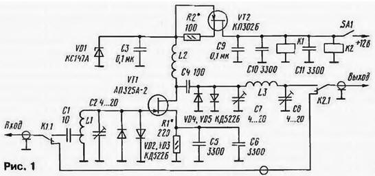
Encyclopedia of radio electronics and electrical engineering / Civil radio communications Radio amateurs widely use multi-channel VHF FM radio stations of industrial manufacture, such as "Mayak" (16R22V-1) and similar ones, to work on the air. However, their sensitivity is not very satisfying to the owners. Trying to increase the sensitivity of the receiving path, many people replace the UHF input transistor (KT399A) with those having a lower noise figure (for example, KT3101A-2, KT3115A-2, KT3132A-2, etc.). But this does not always give a positive effect. According to the authors of these lines, it is possible to significantly increase the sensitivity of the radio station by installing an additional single-stage UHF in it on a low-noise gallium arsenide field-effect transistor. Since extreme sensitivity is not always needed, it is desirable to make an additional UHF switchable to increase the reliability of the radio station. It is this version of the improvement of the Mayak radio station that is proposed in this article. The UHF circuit on a field-effect transistor is shown in Fig. 1. Its gain is 18...21 dB. The sensitivity of the radio station with an amplifier increased to 0,1 μV (with a signal-to-noise ratio of 12 dB and a frequency deviation of 3 kHz).
When the amplifier is de-energized (as shown in the diagram), the input signal through the normally closed contacts of relay K1, a piece of coaxial cable and relay contacts K2 enters the input of the receiving path of the radio station. When the supply voltage is applied, the relay will operate and the signal from the antenna will go to the input circuit L1C2, tuned to the center frequency of the 2 meter range. The amplifying stage is assembled according to the scheme with automatic bias. The value of the drain current is set by the resistor R1. Diodes VD2, VD3 and VD4, VD5, connected in anti-parallel, protect the transistor VT1 from possible breakdown by a powerful signal from the radio station transmitter or static electricity. The amplified signal through the matching P-loop L3C7C8 and relay contacts K2 is fed to the input of the receiving path of the radio station. The UHF is powered by a parametric voltage regulator on the Zener diode VD1 and a current source on the transistor VT2. Depending on the operating voltage, relays K1 and K2 can be turned on in different ways. If it does not exceed 6 V, then their windings can be connected in series. In this case, blocking capacitors C10 and C11 are installed in parallel with the windings. And if the actuation current of each relay is not more than 25 mA, they can be used as a ballast resistor for a zener diode and exclude the field effect transistor VT2 and resistor R2 (see Fig. 2).
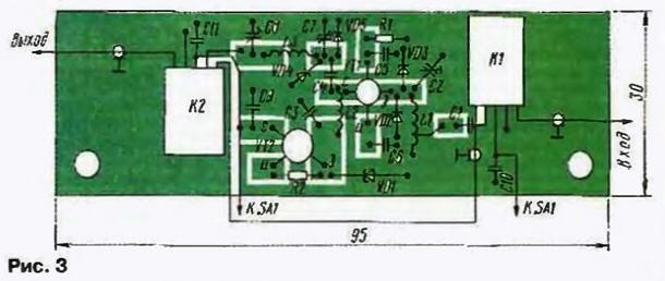
The following parts are applicable in the amplifier: transistor VT1 - AP343A-2, and when changing the topology of the board - AP324A-2, AP331A-2. Trimmer capacitors - KT4-25, and it is desirable to use constant capacitors K10-17v, K10-42. KM, KD, KLS are also suitable, but with minimal dimensions and with a minimum lead length. Resistors - R1-12, R1-4, MLT, S2-33. Relay - RES-49. Coils L1 and L3 are wound turn to turn with PEV-20,9 wire on a mandrel with a diameter of 5 mm. L1 has 4 turns with a tap from 0,5 ... 0,7 turns, L3 - 6 turns. Choke L2 is wound with wire PEV-2 0,3 on a mandrel with a diameter of 3 mm (the number of turns is 12-15). All parts of the amplifier are placed on one side of the printed circuit board made of double-sided foil fiberglass, a sketch of which is shown in Fig. 3. The dimensions of the board were chosen based on the convenience of installing it inside the radio station case. The second side of the board is left metallized and is connected to a common wire along the board contour using foil.
The establishment of the amplifier begins with setting the drain current of the transistor VT2 (within 15 ... 20 mA) by selecting the resistor R2. Then the drain current of the transistor VT1 is set (5mA - for AP325A-2, 10 mA - for APZ31A-2) by selecting the resistor R1. The input circuit is tuned by capacitor C2 to the center frequency of the range. By changing the location of the tap from the coil L1, you can vary the bandwidth of the amplifier input circuit within 2 ... 10 MHz. The P-loop is adjusted to the maximum gain. If the amplifier is self-excited, then a ferrite bead must be put on the drain output of the transistor or a 5 ... 20 Ohm resistor must be connected to the drain circuit. Somewhat worse sensitivity results can be obtained by using low-noise bipolar transistors in the amplifier. A fragment of the scheme of such a UHF is shown in Fig. 4, and the corresponding fragment of the printed circuit board - in fig. 5. In this design, coil L1 is wound with 1,2 mm diameter bare copper wire on a 5 mm diameter mandrel. It contains 6 turns with a tap from the 1st turn. Winding length - 10 mm.
The adjustment begins with setting the required current through the transistor by selecting the resistor R4 to minimize the noise figure (by ear when receiving weak stations). The input circuit with capacitor C2 is set to the middle of the range. In this case, its capacity should be close to the maximum. If this is not the case, then it is necessary to stretch the turns of the coil and repeat the procedure for setting the circuit. In the amplifier, transistors KT3101A-2, KT3114A-6, KT3115A-2 can be used, and with a slight change in the topology of the board - KT3120A-2. The gain of the layout of this amplifier was about 20 dB, and the sensitivity of the radio station with it was 0,12 μV. Placement of UHF in the body of the radio station is shown in fig. 6. Its installation is facilitated by the fact that in the radio station itself the receiver is connected to the power amplifier board with short lengths of wires. Therefore, it is necessary to connect this board to the UHF input with a coaxial cable, and its output with the same cable to the receiver input. +12 V power can be supplied through any small-sized switch, which is placed in a convenient place. The board itself is fixed with screws using the holes in the radio station on the rear wall.
An experimental test of the efficiency of the field-effect transistor amplifier was carried out on a 41 km long path (Kursk - Fatezh, Kursk region). The transmitter power could be changed in 1 dB steps. The test showed that without UHF, for satisfactory signal reception, a transmitter power of 2,5 W was required, and with UHF - 0,25 ... 0,3 W. These numbers speak for themselves. Authors: I. Nechaev (UA3WIA), N. Lukyanchikov (RA3WEO)
The world's tallest astronomical observatory opened
04.05.2024 Controlling objects using air currents
04.05.2024 Purebred dogs get sick no more often than purebred dogs
03.05.2024
▪ Volvo electric buses take to the city streets ▪ Physical activity is good for the brain ▪ Microsoft servers will be equipped with their own processors
▪ section of the site Electrician in the house. Article selection ▪ article Mutual responsibility. Popular expression ▪ article What is the oldest song in the world? Detailed answer ▪ article Leeuwenhoek's microscopes. Children's Science Lab ▪ article LED pn junction probe. Encyclopedia of radio electronics and electrical engineering ▪ article Electrization of the soap bubble. physical experiment
Home page | Library | Articles | Website map | Site Reviews
www.diagram.com.ua |


 Leave your comment on this article: