|
|


 Arabic
 Bengali
 Chinese
 English
 French
 German
 Hebrew
 Hindi
Hindi Italian
 Japanese
 Korean
 Malay
Malay Polish
 Portuguese
 Spanish
 Turkish
 Ukrainian
 Vietnamese
|
ENCYCLOPEDIA OF RADIO ELECTRONICS AND ELECTRICAL ENGINEERING FM receiver on the 430 MHz band. Encyclopedia of radio electronics and electrical engineering
Encyclopedia of radio electronics and electrical engineering / radio reception The development of amateur radio communication on VHF using narrow-band FM is constrained, as noted in [1], primarily by the lack of simple designs of VHF FM receivers, transmitters and transceivers. The described receiver, due to the use of a phase-locked loop detector (PLL) [2], is relatively simple. The device operates in the band 430...440 MHz. Its sensitivity at a signal-to-noise ratio of 10 dB is 0,1 μV. The receiver is built on a superheterodyne circuit with one frequency conversion (Fig. 1). The local oscillator consists of a G1 oscillator with quartz frequency stabilization, which produces oscillations with a frequency of 45 MHz, frequency triplers U3, U4, amplifier A4 and bandpass filters Z5, Z6.
Oscillations with a frequency of 405 MHz from the local oscillator are fed to the mixer W. Station signals are also received here through the input filter Z1. The spectrum of intermediate frequencies converted by the mixer U1 lies in the range of 25...35 MHz. The bandwidth of the IF path (with amplifiers A1, A2) is determined by the filters Z2-Z4. Traditional receiver design further involves the use of a second frequency converter, a tunable second local oscillator, and a narrow-band IF amplifier with an FM detector - in fact, an additional FM receiver is needed. In this device, as a narrow-band FM receiver, a direct conversion receiver with a U2 PLL is used, made on a single transistor [3] and having good sensitivity and selectivity. The schematic diagram of the signal path is shown in fig. 2. The mixer is made on a reverse tunnel diode VD1. The IF amplifier contains two amplification stages of the same type, built according to a cascode circuit on transistors VT1, VT2 and VT3, VT4, respectively. A synchronous phase detector is assembled on the VT5 transistor, which converts the intermediate frequency into sound. The conversion takes place at the second harmonic of the generated oscillations, since the L7C18C20 circuit is rebuilt by the capacitor C20 in the range of 12,5 ... 17,5 MHz. Selectivity is ensured by the action of the PLL: when the local oscillator frequency approaches the half value of the signal frequency of the received station, this frequency is captured and synchronous FM detection occurs [3]. At the same time, the output voltage is 3H, regardless of the level of input FM signals, which is equivalent to the action of AGC, and amplitude modulation and impulse noise are also suppressed. The 3H band (approximately 3 kHz) is determined by the low-pass filter (LPF) R19C17. A higher-order RC or LC low-pass filter can be applied to the receiver output, further improving the signal-to-noise ratio.
The use of only one VT5 transistor instead of a multi-stage FM receiver dramatically reduced the overall noise level of the path. The decisive factor here is that the base of this transistor is connected to a common wire for 3 hours through a high-capacity capacitor C16 (10 microfarads). It has been experimentally established that the capacitance of this capacitor determines the operability of the PLL system. To operate both the local oscillator and the mixer, it is enough that the capacitance is only 10 pF. However, at the same time, the PLL system practically does not work and the level of 000H noise of the transistor VT3 increases sharply. An output sound signal with a level of several tens of millivolts can be fed to a simple 3-hour amplifier. Schematic diagram of the receiver local oscillator is shown in fig. 3. The local oscillator is made according to the traditional scheme for multiplying the frequency of the master oscillator, which is assembled on a transistor VT1 and operates at a frequency of 45 MHz - the third mechanical harmonic of the quartz resistor ZQ1. The cascade on the transistor VT2 is a frequency tripler. Its load is an L2C8 circuit tuned to 135 MHz. The cascade on the transistor VT3 is amplifying. The L3C12 circuit allocates a signal with a frequency of 135 MHz. The second frequency tripler is assembled on a transistor VT4. Its load - the circuit on the elements L4-L6, C17, C 18, C20 - selects a signal with a frequency of 405 MHz and suppresses the by-products of frequency multiplication. 4through the communication circuit C19L7, the signal is fed to the circuit L8C21C22, which further improves the filtering of the output signal spectrum, 4through the communication loop L9, oscillations with a frequency of 405 MHz are fed to the output connector XW1 and then to the mixer.
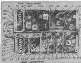
Structurally, the receiver is assembled in two cases made of silver-plated brass (copper) and divided into sections by partitions. The signal block is made by volumetric printed wiring on the board. The local oscillator uses volumetric mounting on support pins isolated from the case with PTFE bushings. The supporting elements for the power circuits are blocking capacitors C5, C7, C9, C11, C13, C15, C16. The location of the main elements in the blocks is shown in fig. 4. The terminals of the elements should be as short as possible, the coils L4, L5 and the lines L6, L8 in the local oscillator block are soldered directly to the terminals of the capacitors C17, C18, C20-C22. To reduce the size of microwave oscillatory systems, in the input circuit of the signal path and the output circuits of the local oscillator, spiral resonators are used, which have a length many times smaller than strip lines [4]. The L1 line in the RF unit is made of a silver-plated copper strip 4 mm wide and 1 mm thick, coiled into a spiral with a diameter of 6,5 mm and a pitch of 2,5 mm. The number of turns in the spiral is 5, the taps are made from the 1st and 4th turns. The L8 line of the local oscillator block is similar, but without taps. Communication loops L7, L9 are made in the form of brackets from pieces of silver-plated copper wire with a diameter of 0,8 and a length of 30 mm (Fig. 4). The L6 resonator is a silver-plated strip measuring 48X4X1 mm. The taps are located at a distance of 6,5 + 9,5 + 16 mm (counting from the end connected to the body).
Coils L2, L3, L5, L7 in the signal block are wound round to round with PEV-2 0,5 wire; L2 contains 5 + 4 turns, L3, L5 - 6 + 4 each, L7 - 12. In the local oscillator, coils L2 and L3 have 2 + 1,5 turns, L4 and L5 - 3 turns each. L2 and L3 are made with a pitch of 2 mm with a silver-plated wire with a diameter of 0,8 mm, L4, L5 - with a pitch of 4 mm with a silver-plated wire with a diameter of 1,2 mm. These coils are wound on polystyrene frames with a diameter of 6,5 mm from the UPCHI paths of unified TVs. Chokes L4, L6 - DM-0,1. Capacitor C20 of the signal unit is made of a tuning capacitor with an air dielectric and an elongated axis; placed directly next to the L7C18 contour. Fixed resistors - MLT. Trimmer capacitors - KPVM, reference - KO-2 or any suitable in size, with a capacity of 1000 ... 6800 pF, the rest - KM, KD. Capacitors C16, C22 in the signal block - K53-1 or K50-6. Instead of the GI401A diode, you can use GI401B, AI402A with any letter index, instead of GT313B transistors - KT3128A, KT3127A, KT328B. Transistor GT31 IE (VT5 in the signal unit) will be replaced by GT311I, KT306B, KT312B, KT316A. The receiver is being adjusted from the signal block. A 1H amplifier is connected to the output connector XW3. Then they connect the power source and make sure that the cascade is working on the VT5 transistor, for which they touch the emitter of the transistor with a screwdriver. With a working transistor, an alternating current background should be heard. Next, an antenna or a standard signal generator (GSS) is connected to the collector of the VT4 transistor and reception is achieved by restructuring the C20C18L7 circuit! amateur radio stations or "GSS carrier frequency in the range of 28 ... 30 MHz. When tuning to the carrier, frequency capture and retention should be observed. If necessary, capacitors C18 and C19 are selected, Achieving stable reception [3]. After that, the antenna or GSS is connected to the base transistor VT3, and then to the connection point of the elements VD1 and C2 and check the operability of the IF path.L2C3C4, L3C8R8, L5C14R16 circuits are configured so that the bandwidth of the IF path is 25 ... 35 MHz, The tuning of the local oscillator block begins with a quartz oscillator - there must be stable generation at the third mechanical harmonic of the quartz resonator. In the remaining stages, the circuits are tuned to the frequencies indicated in Fig. 3. Then the output of the local oscillator block is connected to the mixer of the signal block and, by supplying a carrier frequency in the range of 430 ... 440 MHz to the antenna input from the GSS, the signal is received by tuning the L7C20C18 circuit. After that, the signal level at the receiver input is reduced to the frequency hold failure and, by adjusting the L1C1 circuits in the signal unit and L6C20, L8C21C22 in the local oscillator, a reliable capture and hold of the signal frequency is obtained. These operations are repeated until the minimum value of the input signal is reached, which still ensures the frequency hold. This completes the receiver setup. Literature
Author: A. Mikhelson (UA6AFL), Krasnodar; Publication: N. Bolshakov, rf.atnn.ru
Artificial leather for touch emulation
15.04.2024 Petgugu Global cat litter
15.04.2024 The attractiveness of caring men
14.04.2024
▪ Aluminum film protects against forest fires ▪ Exhibition of domestic robots ▪ Masts to replace power transmission towers
▪ site section Batteries, chargers. Article selection ▪ article All Quiet on the Western Front. Popular expression ▪ What were the features of the emergence of the Ancient Roman state? Detailed answer ▪ article Electrician of station equipment RTU. Standard instruction on labor protection
Comments on the article: Andrei The final stage and the FM detector are essentially "Zakharov's VHF FM receiver" from the Radio magazine. I assembled such a receiver in the 90s and showed terrible instability and sensitivity (the signal level should be tens of millivolts). UPCH gain - maximum 60dB. We consider: 0,1 μV - 3dB = 66nVolt. The input impedance of the first stage is approximately 2000 ohms. Transformation coefficient - square root (2000/50) = 6. Total - 0,4 μV at the input of the IF. We multiply by the amplification factor of the IF 1000 we get - 400 μV. That is, the acceptable signal level at the receiver input should be 10 times higher. Somewhere around 10 microvolts. Otherwise, you will have to make sure that the fly / wind / sun does not knock down the local oscillator and the detector of the "Zakharov VHF FM Receiver" type.
Home page | Library | Articles | Website map | Site Reviews
www.diagram.com.ua |

 Leave your comment on this article: