Prefix for receiving UHF. Encyclopedia of radio electronics and electrical engineering

Encyclopedia of radio electronics and electrical engineering / Телевидение
 Comments on the article
Sufficiently high sensitivity and selectivity is provided by an attachment for receiving decimeter waves (UHF), made according to the above scheme. It is a frequency converter with a separate local oscillator and oscillatory circuits at the input and output.
Rice. 1 (click to enlarge)
UHF television signals through the communication line L1 enter the input circuit L2C1 (it also includes capacitance and mounting inductance). The oscillations selected by him through the capacitor C2 come to the emitter circuit of the transistor VT1 of the mixer. The local oscillator voltage is also supplied here through the capacitor C5. Signals with meter wave frequencies (MB) are emitted in the output circuit of the mixer, formed by coil L4, as well as capacitance and mounting inductance. It is advisable to tune the circuit to the frequency of the first channel MB, since in this case its quality factor will be the highest (due to the maximum inductance of the coil L4). If on the first channel there are television broadcasts or there is systematic interference, the circuit is tuned to the nearest free (second or third) channel. Resistors R1 -R4 and inductor L3 provide the mode of operation of the transistor VT1 for direct current.
The local oscillator is assembled on a transistor VT2 according to the self-oscillator circuit with capacitive coupling. Its oscillatory circuit includes the line L5. capacitors C7, C8. C10, as well as the capacitance of the mounting, the transistor VT2 and the VDI varicap. The DC transistor operation mode is set by resistors R5--R8. The local oscillator is tuned to the required frequency with a variable resistor R10. changing the constant voltage that is supplied to the varicap through the elements R9, L6. With the ratings of the parts indicated on the diagram and the conversion of the UHF signal into the signal of the first channel, the local oscillator frequency is tuned in the frequency range of the 26-37th television channels. If it is necessary to cover another range, the effective inductance of the L5 line should be changed by soldering the terminals of the capacitors C9 and C11 in the direction of shortening or lengthening it. For the same purpose, you can change the capacitance of the capacitor C10 within 0 ... 6 pF and lengthen the terminals of the capacitor C11.
The prefix is powered by a source of stabilized voltage, consisting of a transformer T1, a rectifier (VD3-VD6). parametric voltage stabilizer (VD2.R12) and filter elements (R11, C12. C15, C16). You can also use constant voltages (within 12 ... 150 V) available on the TV. In this case, the transformer and the rectifier bridge are excluded, and the resistance of the resistor R12 (in kiloohms) is determined from the ratio: R12 = Upit-7) / Ipit, where Upit is the voltage (in volts) taken from the TV power supply, and Ipit = 7 mA - the current consumed by the prefix. Naturally, it should be taken into account that the greater the voltage drop across the resistor R12, the greater should be its rated power dissipation.
The prefix used fixed resistors MLT, variable resistor SP-1, capacitors KM-5a (C2, Sat. C9, SI). KT-20 (C1), K10-7B (C3. C4. C13-C15), K.T-1 (C5, C7, C8. C10) and K50 6 (C12, C16). Transistors can be with any current transfer coefficient p;¦e (without selection). Instead of GT341A, it is permissible to use transistors of the KT329 series. GT362, they can also replace the KT306B transistor, but this will require the selection of capacitors C7 and C8.
Coils L1, L2, L5 are made in the form of printed lines. Inductor L3 - DM-0,1 with an inductance of at least 25 μH. Coils L4, L6 are frameless and must contain 22-25 turns of PEV-2 wire with a diameter of 0,35 ... 0,49 mm. They are wound coil to coil on a cylindrical mandrel with a diameter of 2.7 ... 3 mm. Coil trimmer L4 - ferrite (100НН) from the shortwave coil of a transistor radio receiver. The T1 mains transformer can be made on the basis of an output transformer from any tube radio: the plates of its magnetic circuit should be assembled into an overlap, and the secondary winding should be rewound to obtain an alternating voltage of 9 ... 12 V.
The appearance, design and arrangement of parts on the attachment board are shown in Fig. 2-3. All parts except connectors XS1, XS2. variable resistor R10 and capacitor C14 are mounted on a printed circuit board made of foil fiberglass by mechanical means. The contours of the conductors are applied with a thin needle to the foil and cut with a sharp knife along the ruler. Then, peeling off a small piece of foil with a knife, grab it with tweezers and open it. Thus, all unnecessary metal sections are removed.
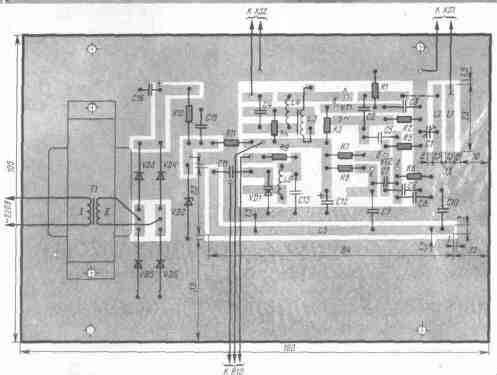
Ris.2
The board is placed in a plastic case with dimensions 175X115X60 mm made of sheet vinyl plastic 2 mm thick (metal can also be used). It can be installed h inside the TV by fixing the variable resistor R10 on the case. In this case, the wires connecting the resistor to the board are placed in a shielding braid, and the capacitor C14 is soldered to its terminals.
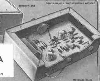
Ris.3
The set-top box is adjusted with weak television signals (for example, when the antenna is turned off) according to the maximum image contrast. If you intend to receive several programs, the input circuit L2C1 is tuned by capacitor C1 to the highest frequency channel. The output circuit is adjusted by changing the inductance of the L4 coil (in the position found, the trimmer is fixed with ceresin or stearin).
Author: N. Katrichev, Khmelnitsky; Publication: N. Bolshakov, rf.atnn.ru
 See other articles Section Телевидение.
Read and write useful comments on this article.
<< Back
 Latest news of science and technology, new electronics:
Energy from space for Starship
08.05.2024
Producing solar energy in space is becoming more feasible with the advent of new technologies and the development of space programs. The head of the startup Virtus Solis shared his vision of using SpaceX's Starship to create orbital power plants capable of powering the Earth. Startup Virtus Solis has unveiled an ambitious project to create orbital power plants using SpaceX's Starship. This idea could significantly change the field of solar energy production, making it more accessible and cheaper. The core of the startup's plan is to reduce the cost of launching satellites into space using Starship. This technological breakthrough is expected to make solar energy production in space more competitive with traditional energy sources. Virtual Solis plans to build large photovoltaic panels in orbit, using Starship to deliver the necessary equipment. However, one of the key challenges ... >>
New method for creating powerful batteries
08.05.2024
With the development of technology and the expanding use of electronics, the issue of creating efficient and safe energy sources is becoming increasingly urgent. Researchers at the University of Queensland have unveiled a new approach to creating high-power zinc-based batteries that could change the landscape of the energy industry. One of the main problems with traditional water-based rechargeable batteries was their low voltage, which limited their use in modern devices. But thanks to a new method developed by scientists, this drawback has been successfully overcome. As part of their research, scientists turned to a special organic compound - catechol. It turned out to be an important component that can improve battery stability and increase its efficiency. This approach has led to a significant increase in the voltage of zinc-ion batteries, making them more competitive. According to scientists, such batteries have several advantages. They have b ... >>
Alcohol content of warm beer
07.05.2024
Beer, as one of the most common alcoholic drinks, has its own unique taste, which can change depending on the temperature of consumption. A new study by an international team of scientists has found that beer temperature has a significant impact on the perception of alcoholic taste. The study, led by materials scientist Lei Jiang, found that at different temperatures, ethanol and water molecules form different types of clusters, which affects the perception of alcoholic taste. At low temperatures, more pyramid-like clusters form, which reduces the pungency of the "ethanol" taste and makes the drink taste less alcoholic. On the contrary, as the temperature increases, the clusters become more chain-like, resulting in a more pronounced alcoholic taste. This explains why the taste of some alcoholic drinks, such as baijiu, can change depending on temperature. The data obtained opens up new prospects for beverage manufacturers, ... >>
| Random news from the Archive In the heat is not up to love
15.11.2015
To the many troubles that await us in connection with global warming, it seems that one can also add a drop in the birth rate - researchers from the US National Bureau of Economic Research (NBER) found that if over the past 80 years, in some season, the temperature in the United States has risen above 26,7°C, then after 10 months the newborns were smaller than usual. In general, writes Bloomberg.com with reference to the working report of economists from the NBER, the fall in the birth rate each time averaged 0,4% from the previous level. And, most importantly, the subsequent rebound was incomplete: the gain was only 32% of the decline. The authors of the study also note that the negative effect of the heat is partly smoothed out since the 70s of the last century, that is, from the time when air conditioning systems began to become widespread.
If, due to global warming, the global temperature continues to rise, then, given the new data, it is easy to imagine what demographic and, therefore, economic consequences await us all. Ecologists can only note with satisfaction that this is a more weighty argument in favor of some kind of active political action than "a decrease in biodiversity on the planet": the connection between biodiversity and human environmental well-being does exist, but it is very difficult to bring it to the consciousness of the "general public" .
Of course, here it would be interesting to know what specific behavioral and / or physiological mechanism links one to the other. Someone will say that in the heat it is not too drawn to love joys, but the whole point may be in some features of the process of fertilization, the fusion of the sperm with the egg, and the subsequent introduction of the embryo into the uterus.
However, recently an article was published in Behavioral Ecology that speaks just in favor of the first explanation. Zoologists from the University of Exeter decided to find out why some female fruit flies mate with many males, while others suffice with one. On the one hand, there is a genetic predisposition to this or that sexual behavior, on the other hand, can the environment contribute?
It turned out, maybe: when it got colder, most females tended to mate with a large number of males, while when it got warmer, they switched to monogamy. (Some, however, remained poly- or monogamous, regardless of the ambient temperature.) Similar variation in sexual behavior can be found in a number of fish, birds, and reptiles, and may also be partly determined by current environmental conditions.
It would be incorrect to directly compare the two works: in one case, we have experiments under strictly controlled conditions, in the other, there is a statistical correlation, which, by the way, may depend on other factors besides temperature; and let's not forget about the difference between Drosophila and humans. But, nevertheless, we all here definitely have something to think about.
|
Other interesting news:
▪ New Toshiba Robot Vacuum Cleaners
▪ Underwater shoulder jetpack CudaJet
▪ Plants produce gasoline
▪ A device for measuring the gravity of an asteroid
▪ New exotic state of matter discovered
News feed of science and technology, new electronics
 Interesting materials of the Free Technical Library:
▪ section of the site Dosimeters. Selection of articles
▪ article What is our life? A game! Popular expression
▪ article What color is a panther? Detailed answer
▪ article Liver of meat and offal. Job description
▪ article Repair and maintenance of CD-ROM drives. Encyclopedia of radio electronics and electrical engineering
▪ article Charger AMT TRAVEL ADAPTER for cell phone. Encyclopedia of radio electronics and electrical engineering
Leave your comment on this article:
 All languages of this page
Home page | Library | Articles | Website map | Site Reviews

www.diagram.com.ua
2000-2024


 Arabic
 Bengali
 Chinese
 English
 French
 German
 Hebrew
 Hindi
Hindi Italian
 Japanese
 Korean
 Malay
Malay Polish
 Portuguese
 Spanish
 Turkish
 Ukrainian
 Vietnamese