|
|
ENCYCLOPEDIA OF RADIO ELECTRONICS AND ELECTRICAL ENGINEERING A simple FM detector. Encyclopedia of radio electronics and electrical engineering
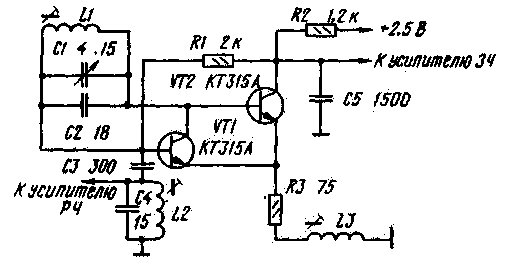
Encyclopedia of radio electronics and electrical engineering / radio reception The reception quality of direct conversion VHF receivers depends mainly on the operation of the FM phase-locked loop (PLL) detector (hereinafter simply the detector). The detector developed by V. Polyakov [1] has good characteristics, but it contains a rather large number of parts and has a relatively high supply voltage (12 V), which makes it difficult to use it in small-sized radio receivers. A simpler detector was proposed by A. Zakharov [2], but, as noted in [3], this detector has low selectivity and noise immunity. One of the reasons for the unsatisfactoriness of these parameters of the detector is, in the opinion of the author of this article, the non-optimal mode of its operation. It is not possible to optimize the operation of the detector by changing the value of positive feedback (POF) in the generator circuits due to the self-excitation of the detector in the audio frequency range. It was possible to eliminate self-excitation by changing the generator circuit and building it on the basis of the local oscillator of an amateur receiver [4]. A schematic diagram of an improved version of the detector is shown in fig. 1. On transistors VT1 and VT2, a two-terminal network with negative resistance is made. Transistor VT2 creates the necessary POS to excite undamped oscillations.
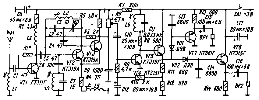
The generation frequency is determined by the parameters of the L1C1C2 circuit and the internal capacitances of the transistors VT1, VT2. Resistor R1 determines the mode of operation of the generator for direct current. Resistor R2. together with capacitor C5 form a low-pass filter with a cutoff frequency of approximately 300 kHz. The depth of the POS is set by the resistor R3 and the inductor L3. The signals of the FM stations are allocated by the broadband circuit L2C4, tuned to the middle frequency of the VHF range, and, through the capacitor C3, are fed to the base of the transistor VT1. The principle of operation of the detector itself is similar to the principle of operation of the detector proposed by A. Zakharov [2], and therefore is not considered here. The optimal mode of operation of the detector is set by selecting the value of the POS according to the minimum interference to radio reception with a sufficient value of the holding band of the received stations. The POS value is adjusted by the inductor trimmer L3. With a high level of received signals, interference is possible due to direct detection of stations adjacent in frequency. This type of interference can be eliminated by choosing the optimal length of the receiving antenna. On fig. 2 shows a diagram of a simple stereo receiver, in which the detector described above is applied. The approximate sensitivity of the receiver is 100 μV, the current consumption does not exceed 8 mA. Two A316 cells are used as power sources. The antenna is a piece of wire 20 ... 30 cm long. Under unfavorable reception conditions, the length of the antenna can be increased to 1 ... 2 m. The input signal selected by the L1C1 circuit, tuned to the middle frequency of the VHF band (69,5 MHz), is amplified by an aperiodic amplifier on the VT1 transistor and fed through the capacitor C5 to the input of the detector on the transistors VT2, VT3. The complex stereo signal (CSS) selected by the detector from the volume control R6 through the capacitor C10 is fed to the input of the CCC amplifier on transistors VT4, VT5. The subcarrier frequency of the CSS is restored by the L6C11 circuit, tuned to a frequency of 31,25 kHz. The KSS amplifier is covered by a deep DC feedback through resistors R9, R10 and capacitor C12. Thanks to this connection, the direct current mode of the KSS amplifier and subsequent stages connected to it galvanically is set automatically. From the output of the amplifier, the KSS enters the input of a polar detector assembled on germanium diodes VD1 and VD2. The subcarrier frequency of the KSS designed by the polar detector is filtered out by capacitors C13 and C14. Emitter followers on transistors VT6 and VT7 match the high output impedance of the polar detector with the low impedance of stereo phones. The base currents of transistors VT6 and VT7 flow through the diodes of the polar detector, as a result, a small bias voltage appears on them. This operating mode of the polar detector makes it possible to reduce nonlinear distortions during detection, as well as to exclude the "mono-stereo" switch from the polar detector circuit when receiving monophonic transmissions [5]. When assembling the receiver, you can use sets of radio components manufactured by the industry. In this version, the receiver housing from the Yunost-KP101 set is used. Under the same set developed printed circuit board (fig. 3). A variable capacitor (KPI), a variable resistor for the volume control, and a ferrite rod for a magnetic antenna were taken from it. KPIs from pocket receivers, as well as from other amateur radio sets with a maximum capacitance of 150 ... 220 pF and variable resistors SP3-3vM are also suitable. During the installation, fixed resistors MLT-0,25 (R2) and MLT-0,125 (the rest), oxide capacitors K50-6 (any other small ones for a voltage of at least 6 V can be used), the rest - KT-1, KT-2, KLS. The functions of the transistor VT1 can be performed by any transistor of the GT311 series. KT315A transistors can be replaced by any low-power high-frequency silicon transistors with a limiting generation frequency when turned on according to the circuit with an OB of at least 200 MHz. With such a replacement, it may be necessary to select a resistor R3. To do this, a variable resistor with a resistance of 4,7 kOhm is soldered in its place and the trimmer of the coil L5 is set to a position in which it is inserted 1/3 of the length of the frame. By changing the resistance of the variable resistor, the generator operation mode is set close to generation failure. In stereo telephones, a lot of noise will be heard. After that, a constant with a close rating is installed in place of the variable resistor. Transistors VT4 - VT7 can be replaced by any low-power silicon transistors of the appropriate structure, having a static current transfer coefficient of at least 60. The spread of this parameter for transistors VT6 and VT7 should not exceed 30%. Coils LI, L3 and L5 contain, respectively, 7, 5 and 7 turns of wire PEV-2 0,62, wound on rods of ferrite 600NN with a length of 12 and a diameter of 2,8 mm. The winding pitch of coils L1 and L5 is 1,5 mm, L3 - 2 mm. Coil L2 contains 15 turns of PELSHO 0,1 wire wound on the body of resistor R2. The L4 coil contains 8 turns of PEV-2 0,62 wire wound on a brass (or aluminum) rod 4 mm in diameter and 10 mm long. Before winding, the rod must be wrapped with two layers of writing paper. Winding step - 1 mm. Coil L6 is wound on a movable cardboard frame, put on a piece of round (diameter 8 mm) or rectangular (20X3 mm) rod made of ferrite 400НН or 600НН 60...120 mm long. Its winding should contain 130 ... 150 turns of PEV-2 0,18 wire, evenly distributed over a frame 25 mm long. For normal operation of the RF amplifier, the resistance of the resistor R1 in kΩ should be approximately numerically equal to the parameter h21e of the transistor VT1. For example, h21e = 40, then R1 = 39 ... 43 kOhm, etc. The remaining stages of the receiver do not require the selection of elements. The voltage at the collectors of transistors VT1 and VT3 should be within 1,2 ... 1,8 V, at the emitter of the transistor VT5 - 1,3 ... 1,5 V. Large deviations from the specified voltage values \u1b\u2bindicate a malfunction of parts or errors in installation. During installation, it is important to observe the polarity of switching on the diodes VD6 and VD7 according to the diagram. Otherwise, emitter followers on transistors VTXNUMX and VTXNUMX will not work. Setting up the receiver begins with tuning it to the required frequency range with the trimmer of the L3 coil. Its position is chosen in such a way that with the help of the KPI it is possible to tune in to all radio stations broadcast in the area. The trimmers of the coils L1, L4, L5 achieve the maximum holding band of the received stations with minimal interfering signals. The L6C11 circuit is adjusted, focusing on the maximum manifestation of the stereo effect, by moving the L6 coil along the ferrite rod. When listening to programs, reception interference may appear in the form of a "rumble", which are associated with the operation of TV scan generators. You can get rid of them by adjusting the input circuit of the receiver accordingly. To do this, it is necessary to shift the turns of the coil L1, and remove the trimmer. In parallel with the L1 coil, a tuning capacitor C * KPK-M with a capacity of 8 ... 30 pF should be soldered (a place is provided for it on the board). The input circuit is tuned with a trimmer capacitor until the interference disappears. It should be noted that the tuning of the input circuit is quite sharp and the signal of the received station often "leaves". Therefore, the tuning operation should be repeated several times, checking the result obtained by ear. The receiver remains operational when the supply voltage drops to 2,5 V. This is a shallow battery discharge, and their performance can be restored by passing a pulsating current through them [6]. The successor can also be powered by two batteries D-0.1 or D-0,25. To do this, it is necessary to exclude the resistor R7 (see Fig. 2), reduce the capacitance of the capacitor C8 to 6800 pF, reduce the resistances of the resistors R13 and R14 to 470 ohms and swap the resistors R11 and R12 in the circuit. The voltage at the emitter of the transistor VT5 in this case will be equal to 1 ... 1,2 V. The modes of other stages of the receiver will not change. Literature 1. Polyakov V. FM detector with PLL acceptance of direct conversion. Radio, 1978, No. 11, p. 41-43.
Author: V.Vlasov, Kaluga; Publication: N. Bolshakov, rf.atnn.ru
Artificial leather for touch emulation
15.04.2024 Petgugu Global cat litter
15.04.2024 The attractiveness of caring men
14.04.2024
▪ The effect of physical education on DNA ▪ There are more microbes in a man's beard than in dog hair ▪ Diesel smoke harms the heart and blood vessels ▪ Microsoft Surface 2 and Microsoft Surface Pro 2 tablets ▪ No antimicrobial additives needed
▪ section of the site Tools and mechanisms for agriculture. Article selection ▪ article Tsvetaeva Marina Ivanovna. Famous aphorisms ▪ article Serpentine head. Legends, cultivation, methods of application ▪ article Prefix for microdrill control. Encyclopedia of radio electronics and electrical engineering
Home page | Library | Articles | Website map | Site Reviews www.diagram.com.ua |


 Arabic
 Bengali
 Chinese
 English
 French
 German
 Hebrew
 Hindi
Hindi Italian
 Japanese
 Korean
 Malay
Malay Polish
 Portuguese
 Spanish
 Turkish
 Ukrainian
 Vietnamese


 Leave your comment on this article: