|
|


 Arabic
 Bengali
 Chinese
 English
 French
 German
 Hebrew
 Hindi
Hindi Italian
 Japanese
 Korean
 Malay
Malay Polish
 Portuguese
 Spanish
 Turkish
 Ukrainian
 Vietnamese
|
ENCYCLOPEDIA OF RADIO ELECTRONICS AND ELECTRICAL ENGINEERING Voltage stabilizer with low minimum voltage drop. Encyclopedia of radio electronics and electrical engineering
Encyclopedia of radio electronics and electrical engineering / Surge Protectors One of the important parameters of serial voltage stabilizers (including microcircuit ones) is the minimum allowable voltage between the input and output of the stabilizer (ΔUmin) at maximum load current. It shows at what minimum difference between the input (Uin) and output (Uout) voltages all the parameters of the stabilizer are within the normal range. Unfortunately, not all radio amateurs pay attention to it, usually they are only interested in output voltage and maximum output current. Meanwhile, this parameter has a significant impact on both the quality of the output voltage and the efficiency of the stabilizer. For example, for widespread microcircuit stabilizers of the 1_M78xx series (xx is a number equal to the stabilization voltage in volts), the minimum allowable voltage is dUmin \u2d 1 V at a current of 7805 A. In practice, this means that for a stabilizer on an LM5 microcircuit (Uout \u7d 1 V), the voltage Uin min must be at least 8 V. If the amplitude of the ripple at the rectifier output reaches 10 V, then the value of Uin min increases to 8,8 V, and taking into account the instability of the mains voltage within ± 57%, it increases to XNUMX V. As a result, the efficiency of the stabilizer will not exceed XNUMX%, and with a large output current, the microcircuit will become very hot. A possible way out is the use of the so-called Low Dropout (with low voltage drop) microcircuit stabilizers, for example, the KR1158ENxx series (ΔUmin \u0,6d 0,5 V at a current of 1084 A) or LM1,3 (Umin \u5d XNUMX V at a current of XNUMX A ). But even lower values of Umin can be achieved if a powerful field-effect transistor is used as a control element. It is about such a device that will be discussed further.
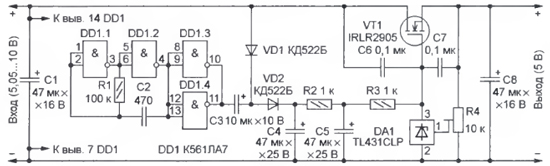
The scheme of the proposed stabilizer is shown in fig. 1. The field effect transistor VT1 is included in the positive power line. The use of a device with an n-channel is due to the results of tests carried out by the author: it turned out that such transistors are less prone to self-excitation and, as a rule, their open channel resistance is lower than that of p-channel ones. Controls the transistor VT1 parallel voltage regulator DA1. In order for the field-effect transistor to open, the voltage at its gate must be at least 2,5 V higher than at the source. Therefore, an additional source is needed with an output voltage that exceeds the voltage at the drain of the field-effect transistor by exactly this value. Such a source - a step-up voltage converter - is assembled on a DD1 chip. Logical elements DD1.1, DD1.2 used in the pulse generator with a repetition rate of about 30 kHz, DD1.3, DD1.4 - buffer; diodes VD1, VD2 and capacitors C3, C4 form a voltage doubling rectifier, resistor R2 and capacitor C5 form a smoothing filter. Capacitors C6, C7 ensure stable operation of the device. The output voltage (its minimum value is 2,5 V) is set by a trimming resistor R4. Laboratory tests of the device layout showed that at a load current of 3 A and a decrease in the input voltage from 7 to 5,05 V, the output decreases from 5 to 4,95 V. In other words, at the specified current, the minimum voltage drop ΔUmin does not exceed 0,1 V. This allows you to more fully use the capabilities of the primary power source (rectifier) and increase the efficiency of the voltage stabilizer.
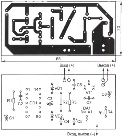
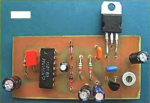
The details of the device are mounted on a printed circuit board (Fig. 2) from one-sided foil fiberglass with a thickness of 1,5 ... 2 mm. Fixed resistors - P1-4, MLT, trimmer - SPZ-19a, capacitors C2, C6, C7 - ceramic K10-17, the rest - oxide imports, for example, the TK series from Jamicon. In a stabilizer with an output voltage of 3 ... 6 V, a field-effect transistor with an opening voltage of not more than 2,5 V should be used. Such transistors from the International Rectifier company usually have the letter L in the marking (see the reference sheet "Powerful field switching transistors firm International Rectifier" in "Radio", 2001, No. 5, p. 45). With a load current of more than 1,5 ... 2 A, it is necessary to use a transistor with an open channel resistance of not more than 0,02 ... 0,03 Ohm. To avoid overheating, the field-effect transistor is fixed on a heat sink, and a board can be glued to it through an insulating gasket. The appearance of the mounted board is shown in fig. 3.
The output voltage of the stabilizer can be increased, but one should not forget that the maximum supply voltage of the K561LA7 microcircuit is 15 V, and the limit value of the gate-source voltage of the field-effect transistor in most cases does not exceed 20 V.
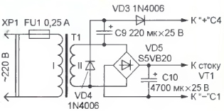
Therefore, in such a case, you should use a boost converter assembled according to a different scheme (on an element base that allows a higher supply voltage), and limit the voltage at the gate of the field-effect transistor by connecting a zener diode in parallel with capacitor C5 with the appropriate stabilization voltage. If the stabilizer is supposed to be built into a power source with a step-down transformer, then the voltage converter (DD1 microcircuit, diodes VD1, VD2, resistor R1 and capacitors C2, C3) can be excluded, and the "main" rectifier on the VD5 diode bridge (Fig. 4) can be supplemented with a doubler voltage on the diodes VD3, VD4 and capacitor C9 (the numbering of the elements continues what was started in Fig. 1). Author: I. Nechaev, Moscow; Publication: radioradar.net
Artificial leather for touch emulation
15.04.2024 Petgugu Global cat litter
15.04.2024 The attractiveness of caring men
14.04.2024
▪ Geoengineering weather control ▪ Viruses and algae can cause clouds ▪ Non-contact emotion recognition system
▪ section of the site Security and safety. Article selection ▪ Article State within a State. Popular expression ▪ article Perfect loop. Travel Tips ▪ article 100-watt amplifier PA100GC. Encyclopedia of radio electronics and electrical engineering ▪ article Underground economy of the illusionist in the circus. Focus Secret
Home page | Library | Articles | Website map | Site Reviews
www.diagram.com.ua |

 Leave your comment on this article: