|
|
ENCYCLOPEDIA OF RADIO ELECTRONICS AND ELECTRICAL ENGINEERING Two emergency overvoltage protection devices. Encyclopedia of radio electronics and electrical engineering
Encyclopedia of radio electronics and electrical engineering / Protection of equipment from emergency operation of the network, uninterruptible power supplies The most dangerous for electrical appliances and radio equipment is an emergency increase in mains voltage. This can happen when an open overhead wiring in a power line breaks due to a strong wind and one of the phase wires closes to zero. At the same time, a voltage of up to 380 V can operate in the network for some time. The included light bulbs burst, and all other radio-electronic devices fail. This is most likely in the countryside or in the country, although there have been cases in the city. Although this happens very rarely, it does not make it any easier for those who have suffered. The fuses or electromechanical circuit breakers located at the mains input to the apartment only operate when the specified current is exceeded (usually in the event of a short circuit in the circuit). And the current in the circuits increases significantly already in the event of damage to electrical appliances and radio equipment. This is explained by the fact that with an increase in the mains voltage by 50%, the dissipated power in energy consumers increases by more than 2 times (P=U^2/R). Many household electrical appliances (electric heaters, lighting lamps, refrigerators, etc.) are not afraid of low voltage in the network. For them, the following two schemes are mainly intended. They work only when the supply voltage rises above a given threshold and differ in their speed, and hence the scope. The simplest circuit that can provide protection for lighting lamps or heaters in the event of an emergency voltage increase in the network is shown in fig. 1. In the initial state, the value of the resistor R1 is selected so that the relay K1 is turned off. Through groups of normally closed contacts K1.1, K1.2, voltage is supplied to the load.
As relay K1, almost any winding operating voltage of 220 V or less can be used (the permissible current through the contacts must be at least 3 ... 5 A, for example, from the RPU series). The value of the resistance of the resistor R1 depends on the resistance of the relay winding, as well as its design (it is selected so that K1 can work when the operating voltage in the network rises above 260 V). When the relay is triggered, the load circuit will open, and an additional resistor R2 with a group of contacts K1.2 will be connected. Resistor R2 will allow the relay to be stably kept on. Its value determines at what level of undervoltage the relay will return to its original state (turn off). In order to eliminate the bounce of contacts K1.1 when the voltage approaches the threshold value, it will be necessary to bend the contacts K1.2 so that they work earlier than K1.1. The disadvantage of this circuit is the low response speed, which is why it cannot reliably protect non-inertial household appliances and radio equipment. The second circuit, fig. 2. It is powered directly from the mains and must be connected in standby mode at all times. The device has a low current consumption in standby mode - about 2 mA, and when the protection is triggered - no more than 100 mA.
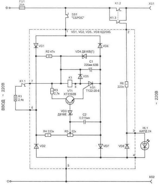
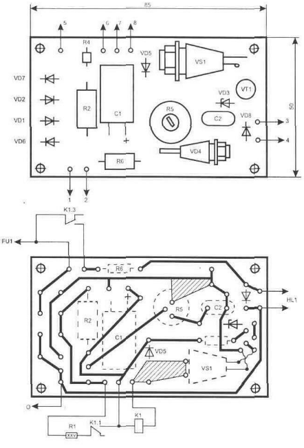
In the initial state, the relay K1 is not turned on and energy is accumulated on the capacitor C1 due to its charge from the network through the resistor R2. In this case, the voltage on C1 will exceed the required nominal for the operation of the relay by 30 ... 50%. This allows you to speed up the operation of the turnip. Zener diode VD1 limits the voltage across capacitor C1 to 33 V (without it, the voltage can reach 340 V). With an increase in the voltage in the network, as soon as it exceeds the opening threshold of the zener diode VD5 on the resistor R3, the transistor VT1 and the thyristor VS1 open. Due to the energy accumulated on the capacitor C1, the relay K1 is activated. Contact group K1.1 connects resistor R1 in parallel with R2. The current passing through it allows you to keep the relay in the on state after operation, when the capacitor is discharged through the relay winding. Here, a feature of electromagnetic relays is used - to keep the contacts in the on state, less current is required than to turn on. Therefore, switching on is carried out at an increased voltage, and holding is carried out at the minimum necessary - this is approximately 18 V for the TKE54 type. Load disconnection is performed by groups of normally closed contacts of relay K1 (they are connected in parallel to increase the allowable passing current). Capacitor C2 prevents operation of protection against short-term interference in the network. The protection operation indicator is the glow of the HL1 LED. Diode VD8 protects the LED from exposure to high reverse voltage. In the event of a protection trip, you can return the circuit to its original state by pressing the "reset" button (SB1). The circuit used details: a 1 W PEV resistor R25, and the rest are fixed resistors of the MLT type with the corresponding dissipation power (it is indicated in the diagram). Trimmer resistor R5 type SP5-16A-1 W. Capacitors C1 type K50-35, C2 - K10-17. As diodes VD1, VD2, VD5 ... VD7, any rectifiers for a current of 0,5 A and a reverse voltage of at least 400 V are suitable. The VT1 KT3102 transistor can be replaced with KT315 or KT312. The zener diode VD3 is replaced by any of a series of precision ones with a stabilization voltage of 6,6 ... 9,1 V, VD4 on the KS533A. The HL1 LED is suitable for any of the KIPD or AL310A series. Instead of an LED, it is also convenient to use neon. Thyristor VS1 can be used from the T112 or T122 series, for example T122-20-6 (the last digit in the designation indicates the class of permissible reverse voltage and does not matter in this circuit). Relay K1 can be of type TKE54POD or more modern from the RNE44 series. Such relays allow switching a voltage of 220 V and allow a current of more than 10 A to pass through their contacts, and even more when they are connected in parallel. All elements in the diagram, highlighted by a dotted line, except for relay K1, are located on a printed circuit board made of one-sided fiberglass 1.5 ... 3 mm thick with dimensions of 85x50 mm, fig. 3.
To configure the device, you will need LATR, which allows you to increase the voltage at the input of the circuit to 260 V. The level of increased mains voltage at which the protection is triggered is set by resistor R5. The value of the resistor R6 depends on the type of LED HL1 used and is selected to obtain the desired brightness of the indicator.
Machine for thinning flowers in gardens
02.05.2024 Advanced Infrared Microscope
02.05.2024 Air trap for insects
01.05.2024
▪ Xiaomi Mijia Braun Waterproof Electric Shaver ▪ Spent spacecraft stages are returning ▪ Compact Optical Mouse by Microsoft ▪ LEDs that emit tangled light
▪ section of the site Mobile communications. Article selection ▪ Article Faster, Higher, Stronger! Popular expression ▪ article What celestial object accompanied the birth and death of Mark Twain? Detailed answer ▪ article Three-leaf watch. Legends, cultivation, methods of application ▪ article Weights for crafts. Simple recipes and tips ▪ article Thyristor voltage stabilizer. Encyclopedia of radio electronics and electrical engineering
Home page | Library | Articles | Website map | Site Reviews www.diagram.com.ua |


 Arabic
 Bengali
 Chinese
 English
 French
 German
 Hebrew
 Hindi
Hindi Italian
 Japanese
 Korean
 Malay
Malay Polish
 Portuguese
 Spanish
 Turkish
 Ukrainian
 Vietnamese


 Leave your comment on this article: