|
|


 Arabic
 Bengali
 Chinese
 English
 French
 German
 Hebrew
 Hindi
Hindi Italian
 Japanese
 Korean
 Malay
Malay Polish
 Portuguese
 Spanish
 Turkish
 Ukrainian
 Vietnamese
|
ENCYCLOPEDIA OF RADIO ELECTRONICS AND ELECTRICAL ENGINEERING Repair and modification of chargers NS-307 and NS-314. Encyclopedia of radio electronics and electrical engineering
Encyclopedia of radio electronics and electrical engineering / Chargers, batteries, galvanic cells Somehow, after severe winter frosts, a sale of substandard chargers (chargers) of the Nasha Sila trademark for Ni-Cd and Ni-MH batteries of AAA and AA sizes was arranged on the Kharkov radio market. The main defect was the lack of indication, the charging function was performed normally. ZU NS-307 and NS-314 were purchased at a reduced price. According to the description, the first of them allowed charging one or two batteries with a current of 750 mA. In the second, the maximum number of batteries is increased to four, and the charging current is 800 ... 1000 mA. It also provides pre-discharge of batteries. Both chargers have economical switching power supplies and allow you to simultaneously charge batteries of different capacities and different sizes.
As expected at the time of purchase, in both memory devices, the LCDs failed due to severe frosts. On the HC-314 indicator, there were four battery circuits with three filling levels for each (Fig. 1), as well as the inscriptions CHARGE (charging) and REFRESH (discharging). On the NS-307 there were only two "batteries" without inscriptions. According to the instructions attached to the charger, the first level of filling corresponds to charging the battery by 50% of the nominal capacity, the second - by 75%, the third - by 100%. Since such LCDs were not found on sale, the idea arose to replace them with similarly sized, self-made LED indicators.
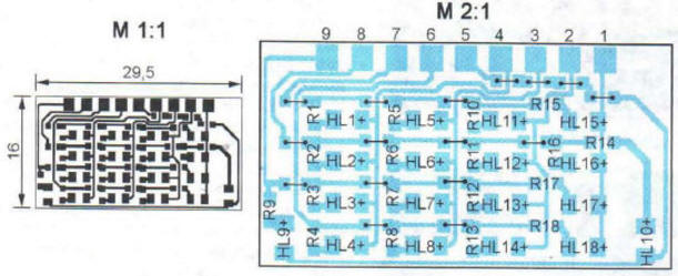
The scheme of the LED indicator developed for the NS-307 charger is shown in fig. 2. Green LEDs HL4 and HL8 perform the same role as the battery circuits on the LCD. Their inclusion indicates the presence of a battery in the corresponding contact device. Instead of the quadrangles that fill the contours of the batteries, yellow LEDs HL1 - HL3 and HL5-HL7 are used. To achieve the same brightness of LEDs of different colors, the values of the resistors connected in series with them are chosen different.
The indicator is mounted on a single-sided printed circuit board made of foil fiberglass, shown in fig. 3. Its dimensions are exactly the same as the replacement LCD. The appearance of the assembled board from the installation side is shown in fig. 4. LEDs in rectangular cases with a cross section of 2x5 mm are inserted from the side of the printed conductors into the holes cut out in the board. Resistors are SMD size 0805. There is one size 1206 jumper.
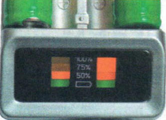
The front surface of the printed circuit board is painted black, a transparent film with white inscriptions is pasted on it. A new indicator is connected instead of a faulty LCD to the charger board. The names of the connection points are given both on the circuit diagram and on the layout of the indicator elements. The LED indicator installed in the memory and working is shown in fig. 5.
The scheme of the developed LED indicator for the NS-314 charger is shown in fig. 6. The battery circuits here are replaced by green LEDs HL4, HL8, HL14 and HL18. The ongoing charging process is signaled by the red HL10 LED, and the green HL9 is signaling the discharge process. The remaining 12 blue LEDs indicate the charge status of the batteries.
Due to the small dimensions of the replaced LCD and the need to place it on the board shown in Fig. 7. A large number of elements, all of them - for surface mounting, standard size 0805 or 0603, including 16 jumpers. The assembled board is installed in the memory in place of the soldered-out LCD. The working memory NS-314 with LED indicator is shown in fig. 8. The actual value of the battery charging current measured in the NS-307 charger turned out to be 620 mA, and in the NS-314 charger it was about 770 mA. When discussing battery issues on Internet forums dedicated to digital cameras, the author repeatedly encountered unfavorable reviews about chargers with a charging current of 500 ... 1000 mA. As they say, a large charging current (more than 0,2 C) "kills" batteries in just a few tens of cycles. After that, the rate of their self-discharge increases significantly, although the capacity practically does not decrease. The probable cause is called a significant overheating of the batteries by increased charging current. Indeed, in simple memory, the temperature of the battery being charged is not controlled. But with the help of a charger with a charging current of 200 mA, batteries are repeatedly charged without any negative consequences for them.
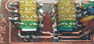
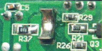
For this reason, it was decided not only to replace the indicators in the purchased chargers, but also to reduce the charging current to 200 ... 250 mA. It turned out to be quite simple to do this, since in the NS-307 and NS-314 chargers all the batteries for charging are connected in series, and the charging current is set by just one resistor. In NS-307, this is R37 of size 1206 (Fig. 9). Its nominal value is 0,18 ohms, the voltage drop during charging is 115 mV. It was replaced by two 0805 size 1 ohm resistors connected in parallel. The charging current has decreased to 230 mA.
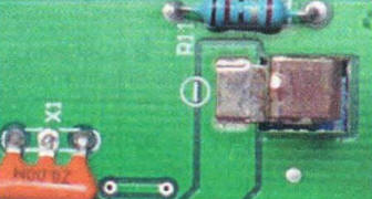
In the NS-314 charger, the current sets the resistor R11 (Fig. 10) of a conventional design with a nominal value of 0,1 Ohm. The voltage drop across it is 73 mV. It was replaced by a similar 0,3 ohm resistor, which also reduced the charging current to 230 mA. Modified memory proved to be reliable and easy to use. No deterioration in the parameters of the batteries after several tens of charging cycles was noticed. Author: S. Samoilov
Machine for thinning flowers in gardens
02.05.2024 Advanced Infrared Microscope
02.05.2024 Air trap for insects
01.05.2024
▪ The blackest color for a BMW car ▪ Ingenic tablet with Android 4.0 for $120 ▪ Happiness from altruism is short-lived ▪ Biodegradable displays for green electronics
▪ section of the website Basics of First Medical Aid (BFA). Selection of articles ▪ article Hot spot, Hot spots. Popular expression ▪ article When did ballet appear? Detailed answer ▪ Anil article. Legends, cultivation, methods of application
Comments on the article: Vasil I have been using the HC-307 charger since 2006. It works great, but the batteries and the case get very hot. The disadvantage is that AA batteries - AAA are charged with a large - the same current - C / 0.5 ... C / 2, which AA can still withstand, but AAA cannot. To do this, I disconnected the minuses of AA from AAA - for each type I put my own resistor R37 / 1 R37 / 2 in the current C / 10. Accordingly, 240/100 mA - you can choose within 160 ... 300 / 50 ... 120 mA, depending on the capacity of the batteries you are working with.
Home page | Library | Articles | Website map | Site Reviews
www.diagram.com.ua |


 Leave your comment on this article: