|
|


 Arabic
 Bengali
 Chinese
 English
 French
 German
 Hebrew
 Hindi
Hindi Italian
 Japanese
 Korean
 Malay
Malay Polish
 Portuguese
 Spanish
 Turkish
 Ukrainian
 Vietnamese
|
ENCYCLOPEDIA OF RADIO ELECTRONICS AND ELECTRICAL ENGINEERING Powerful bipolar voltage stabilizer for UMZCH. Encyclopedia of radio electronics and electrical engineering
Encyclopedia of radio electronics and electrical engineering / Surge Protectors The author proposes a bipolar supply voltage regulator, suitable for amplifiers with power up to 50-100 W per channel. The device is made on powerful field-effect transistors capable of operating with multiple short-term current overloads. The use of such stabilizers is largely justified in amplifiers with high sensitivity to changes and ripples in the supply voltage, which is especially characteristic of simple amplifiers without general feedback. As you know, a separate power supply is used to power the powerful UMZCH output stage in a number of designs, and the rest of the amplifier is powered by a voltage stabilizer. Most of these power supplies are unregulated and consist of two full-wave rectifiers (for positive and negative polarity voltages) with a midpoint with smoothing capacitors. This unregulated voltage is not used by the rest of the amplifier if it has additional nodes and a signal source switch (full, "integral" amplifier). In addition, the general feedback used in most UMZCH significantly reduces the sensitivity to supply voltage ripples. And if the depth of the general environmental protection is small or not at all, the ripple of the supply voltage can be heard through the acoustic systems. The cardinal way to suppress ripple and instability is to supply the output stages of the amplifier with a stabilized voltage, however, the use of integral stabilizers also encounters a number of problems. The fact is that such stabilizers have a relatively large voltage drop. In addition, they, as a rule, have built-in current and power limiters, which can generally negate the advantages of the stabilizer. You can, of course, use an integrated high-power stabilizer (for example, with an output current of 10 A), but its cost, in my opinion, is unacceptable. An alternative in solving this problem can be the use of powerful field-effect transistors in the supply voltage stabilizer. These transistors, by the way, are inexpensive and have a low open channel resistance (hundredths of an ohm) and a maximum current of up to 70 ... 100 A, which allows you to design stabilizers with a very low voltage drop (no more than 0,25 V) at a current of up to 20 A . The parameters of the described stabilizer are as follows. With an output voltage of 27 V, its maximum current reaches 4,5 A. With this load current, the minimum operating voltage between input and output does not exceed 0,25 V. The difference between the output voltage of the stabilizer without load and the voltage at a load current of 4,5 A is no more than 0,15 V, with a current of 6 A, this difference does not exceed 0,16 V. Such parameters of the stabilizer are provided by the powerful field-effect transistors used in it - IRF4905 (p-channel) with a maximum drain current of 74 A and an open channel resistance of 0,02 Ohm and IRL2505 (n-channel), with a corresponding current of 104 A and a resistance of 0,008 Ohm.
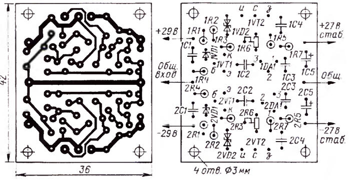
A bipolar stabilizer consists of two independent voltage sources of positive and negative polarity (Fig. 1). The upper part of the circuit refers to the positive polarity stabilizer, and the lower part refers to the negative polarity. For ease of comparison, the numbering of the corresponding elements differs only in prefixes 1 and 2. First, about some features of the stabilizer. It has three critical elements - these are capacitors C2 and C3 and a zener diode VD1. The capacitance values of capacitors C2 and C3 indicated in the diagram are, in a sense, a compromise: when they decrease, the possibility of self-excitation of the stabilizer arises. An increase in their capacitance to 1 μF leads to the fact that ripples, which are always present in the rectified voltage, penetrate the output of the stabilizer. Now a few words about why the Zener diode VD1 (BZX55-C7V5) with a stabilization voltage of 7,5 V was chosen. It is advisable to choose a Zener diode whose differential resistance is minimal (it affects the properties of the entire stabilizer). Of all the zener diodes of the BZX55 series, the zener diodes BZX7-C55V7 and BZX5-C55V8 have the smallest differential resistance (2 ohms). If the input voltage of the stabilizer is less than 20 ... 25 V, it is advisable to use a zener diode for a voltage of not more than 3,3 V (for example, BZX55-C3V3). The negative polarity stabilizer circuit with slight changes was borrowed from [1] and was already once used by me for a drill speed controller (with a current margin of 20 ... 30 A). Compared with the circuit from [1], in the circuit in Fig. 1, the values of some capacitors and resistors have been changed, a VD2 zener diode has been added to protect the VT2 gate from breakdown, and a zener diode (VD1) has been used for a different stabilization voltage (7,5 V). The positive polarity stabilizer circuit is a mirror image of the negative polarity stabilizer circuit Instead of the n-channel one, it uses the IRF4905 p-channel field-effect transistor in the TO-220 (VT2) package, instead of the p-n-p bipolar transistor, the npn structure transistor BC337-40 or KT503B (VT1), and the load of the parallel stabilizer DA1 (TL431CZ in the TO-92 package) is included in its anode circuit. Although this load is less known, it is most common in switching power supplies for computers. A few notes on how the described stabilizer can be modified for use at a supply voltage of +/-35 ... 45 V. In this case, the resistance of the resistor R4 (620 Ohm) must be increased to 0,9.. DA1 (TL1CZ) did not exceed half of its maximum current of 431 mA. Instead of a complementary pair of transistors VS50 / VS327 (Uke max = 337 V, Ikmax = 45 A, PKmax = 0,8 W), you should use a pair with a slightly higher voltage iKe max. for example, 2SA1284 / 2SC3244 (UK3max = 100 V, lKmax = 0,5 A, PKmax = 0,9 W). It is desirable to install field-effect transistors on heat sinks with a large cooling area. It should also be added that in order to set the desired stabilization voltage, it will be necessary to change the values of resistors R5, R6 and R7. It is desirable to use a zener diode for a stabilization voltage of 7,5 V (BZX55-C7V5). I recommend purchasing the TL431CZ chip manufactured by National Semiconductor, Texas Instruments, Vishay, Motorola. All resistors, except for the trimmer R6 (SPZ-19A), have a power of 0,25 W, ceramic capacitors - for a voltage of 50 V.
Since I needed two boards of a bipolar stabilizer (one for each UMZCH channel), using the Sprint Layout 5.0 program, I laid out the printed wiring of the board (Fig. 2 printed its drawing on tracing paper intended for printing with a laser printer, and made it using the method described by me in [2, 3] The appearance of the mounted board is shown in Fig. 3
To test the operation of the stabilizer, I used three digital multimeters, two of which measured the input and output voltages of the stabilizer, and the third in ammeter mode measured its output current. It should be added here that the circuit in Fig. 4 is used to test the positive voltage stabilizer. The properties of the negative voltage stabilizer were tested in a similar way.
As a load (R1), a ceramic resistor SQP with a power of 20 W with a resistance of 1 Ohm was used, and as R2 - a PE-75 resistor with a power of 75 W with a resistance of 5 Ohms. Thus, the total load resistance (6 ohms) of the stabilizer corresponded to a total power of 95 watts. and the current is 4,5 A. When testing the stabilizer, I used a modified stabilized B5-47 power supply as a power source, in which the output voltage (up to 30 V) is provided at a load current of up to 4 A (up to 5 A without modification). To increase the current limit to 3 A, it is necessary to install jumpers between contacts 4,59, 23, 24 and 26 in the remote control connector located on the rear wall of the unit, and set the maximum current value of 50 A on the front panel The results of testing the operation of stabilizers fully confirmed their parameters. The stabilizers have a significant current margin, and the power in the load of each of the stabilizers corresponds to 121,5 W, which is 243 W in total. If the power of one channel of the amplifier P = 35 W, and the load resistance R = 4 Ohm, then the amplitude of the signal voltage U "17 V and current lm = 4,25 A. This means that if the stabilizer is bipolar and consists of stabilizers of positive and negative polarity , each of them must provide a maximum current of 4,25 A. If the output voltage of the stabilizer is 27 V and the current in the load is 4,25 A, then the equivalent load corresponds to the resistance ReKB = 6,35 Ohm. That is why the load resistance of the stabilizer, equal to 6 ohms, was chosen. When testing, a real power supply rectifier with a high current and a high level of ripple was also used (a storage capacitor with a capacity of 10000 μF and rectifier diodes DSS 60-0045V (Uobr = 45 V, lmax = 60 A, Upr = 0,35 V / 10 A), included in the bridge circuit. The described stabilizer is also resistant to short-term overloads. I used it to adjust the speed of rotation of a drill, in which the starting current of the motor reaches 20 A. Thus, the stabilizer has a significant current margin, which allows it to be used with large heat sinks and in more powerful UMZCH Now a few words about installing and adjusting the stabilizer in the amplifier First of all, it is necessary to evaluate using an oscilloscope the minimum values of the supply voltage of the UMZCH output stages at maximum load. To do this, connect a resistor to the UMZCH output with a nominal value equal to the AC resistance (4 or 8 Ohms) and a power corresponding to the maximum for the UMZCH. Apply a signal with a frequency of 34 ... 20 Hz from the generator 30 to the amplifier input, and set the signal level corresponding to the volume control the maximum power of the amplifier. Next, you need to determine the minimum absolute value (taking into account the amplitude of the ripples) of the supply voltages and set the stabilization voltage with a tuning resistor R6 by approximately 1 V less than this minimum value in each of the stabilizers. Before installing two boards of such stabilizers in each of the channels in the amplifier ("Kumir U-001"), I replaced the KD208A diodes (Unp = 1 V / 1.5 A) in the bridge rectifiers of the power supplies with MBR10100 Schottky diodes (Unp = 0,45 V / 1,5 .209 A) and KD30A diodes in a 503 V voltage regulator with HER30 diodes. In addition, the capacitance of the smoothing capacitors was doubled (both in the rectifiers of the output stages and in the XNUMX V stabilizer). After installing the stabilizers in the case and turning on the amplifier, it is necessary to check and adjust the balance of the output stages for direct current, and then the quiescent current of powerful transistors Having adjusted the operating modes of the transistors of the UMZCH output stages with installed stabilizers, I found a noticeable decrease in the background even at maximum sensitivity in the absence of an input signal. Literature
Author: A.Kuzminov
Artificial leather for touch emulation
15.04.2024 Petgugu Global cat litter
15.04.2024 The attractiveness of caring men
14.04.2024
▪ Bigger brain - higher risk of mental illness ▪ The car recognizes the face of the driver ▪ The world's largest wave power plant will be built ▪ Raising a dog is like raising a child.
▪ section of the site Car. Article selection ▪ article by George Herbert. Famous aphorisms ▪ article Which of the creatures living on Earth is the oldest? Detailed answer ▪ article Niagara Falls. Nature miracle ▪ article Bastom Drum Simulator Module. Encyclopedia of radio electronics and electrical engineering ▪ article Knot on a rope. Focus Secret
Home page | Library | Articles | Website map | Site Reviews
www.diagram.com.ua |


 Leave your comment on this article: