|
|


 Arabic
 Bengali
 Chinese
 English
 French
 German
 Hebrew
 Hindi
Hindi Italian
 Japanese
 Korean
 Malay
Malay Polish
 Portuguese
 Spanish
 Turkish
 Ukrainian
 Vietnamese
|
ENCYCLOPEDIA OF RADIO ELECTRONICS AND ELECTRICAL ENGINEERING Soldering iron power supply voltage 36 V. Encyclopedia of radio electronics and electrical engineering
Encyclopedia of radio electronics and electrical engineering / Power Supplies The article describes a pulse unit with a rated output voltage of 36 V to power loads up to 25 W. The device provides the ability to quickly switch to an output voltage of 29 V. In the author's version, the unit is used to power a low-voltage soldering iron, but it can be used for any load of the appropriate power, designed for a voltage of 36 V. Today, to work with modern microelectronics, small-sized soldering irons designed for voltages from 6 to 36 V are widely used. To work with them, you need a separate power supply. "Classic" blocks with network transformers are quite bulky, at the same time it is easy to make a flyback switching power supply (SMPS) yourself using a modern element base. The proposed version of the power supply is designed to work with soldering irons with an operating voltage of 36 V and a power of up to 25 W. The device provides for a stepwise decrease in the soldering iron supply voltage to 29 V, which corresponds to a decrease in soldering iron power by up to 70%. Main Specifications
The power supply largely repeats the previously described SMPS for a 6 V soldering iron in the article "Power Supply for a 18 W Low-Voltage Soldering Iron". When repeating the proposed device and any questions arise, I recommend that you read this article and the literature indicated in it. On fig. 1 shows a diagram of an SMPS for a soldering iron. The basis of the device is a specialized TOP224Y chip.
The SMPS is assembled on a printed circuit board made of fiberglass laminated on one side with a thickness of 1,5 ... 2 mm. Its drawing is shown in Fig. 2. In order to reduce the size, the device uses imported oxide capacitors. Capacitor C5 - ceramic or film for a rated voltage of at least 400 V, the rest - ceramic for a voltage of at least 50 V. Inductor L1 is wound on a "dumbbell-shaped" ferrite magnetic circuit measuring 9x12 mm from a faulty personal computer power supply with a PEV-2 wire 0,25 before filling. The inductor L2 is wound on a ferrite rod with a diameter of 6 and a length of 15 mm and contains 14 turns of PEV-2 0,7 wire. Both chokes are installed perpendicular to the board. Recommendations for possible replacement of used parts can also be found in the above article.
The converter microcircuit is mounted on a heat sink made of 1 mm thick copper sheet. The use of copper made it very easy to manufacture a heat sink with a maximum cooling surface due to the flexibility of the material. The shape and dimensions of the heat sink can be judged by the appearance of the device board shown in Fig. 3.
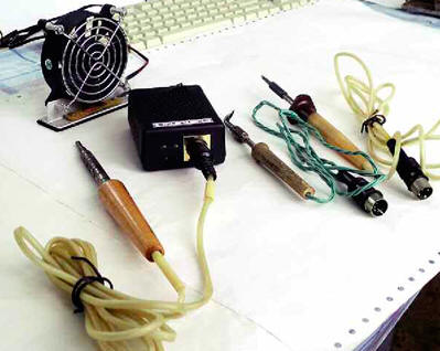
The device is assembled in a BOX-KA12 case with dimensions of 90x65x35 mm. Holes are drilled in the case for cooling. The power switch is located on the top cover, the LEDs are mounted on a separate small board and glued to the cover. LED HL2 - green glow, HL1 - red, the latter is turned on by switch SA2 when the latter is set to low output voltage mode. Finished products are used in the SMPS: switch SA2 - B1550 (SS8) imported slide switch for two positions of horizontal design. XP1 power connector - RF-180S plug per unit, angled two-pin 250 V/2,5 A, output connector - five-pin DIN5 per board. Power switch - SC719 (SMRS-101), 250V/1A or equivalent. The converter transformer is assembled on an E30/15/7 E30/30/7 1500x2000x1 mm magnetic core with a low-profile frame made of ferrite, presumably with a permeability of 1300...0,2. A set of a frame and a magnetic circuit was purchased at a store where there is no exact information about the parameters of the ferrite. Therefore, as in [82], I set the value of the inductance of the primary winding to 2 μH and first wound a test winding. After measuring the inductance, taking into account the gap at the edges of 0,38 mm, the transformer was recalculated and the following parameters were obtained: the primary winding (I) contains 10 turns of PEV-2 wire with a diameter of 0,15 mm; communication winding (II) - 36 turns of wire PEV-2 0,7; output winding (III) - 0,2 turns of wire PEV-5 5. Non-magnetic spacers 0,1 mm thick are installed in the extreme cores of the magnetic circuit. Sometimes the magnetic circuits already have a ready-made gap, then gaskets are not needed. All windings are insulated from each other with a double layer of TEA XNUMXKXNUMX polyester insulating tape, which can be replaced with varnished cloth or other insulating material with a total thickness of XNUMX mm. After final assembly, the inductance of the primary winding should be checked. When you first turn it on, you must use a 1-40 W incandescent lamp instead of the FU60 fusible insert. This will save you from possible troubles. After final assembly, the power supply was tested with 10W, 15W, and 25W soldering irons. In the latter case, the internal volume of the case was not enough for effective cooling. I had to use forced cooling of the unit for a 25 W soldering iron (Fig. 4).
Author: S. Chernov
Artificial leather for touch emulation
15.04.2024 Petgugu Global cat litter
15.04.2024 The attractiveness of caring men
14.04.2024
▪ Butterfly saves not the pattern of eyes on the wings ▪ AOC AGON PRO AG274QGM Gaming Monitor ▪ Restoration of the appearance of a person by his DNA ▪ Acer ConceptD 7 SpatialLabs Edition XNUMXD laptop ▪ The oceans are losing oxygen
▪ site section Regulators of current, voltage, power. Article selection ▪ article What is idealism? Detailed answer ▪ Article Head of Sales. Job description ▪ article Amplifier on the chip TDA7294. Encyclopedia of radio electronics and electrical engineering ▪ article Radio receiver Ant. Encyclopedia of radio electronics and electrical engineering
Home page | Library | Articles | Website map | Site Reviews
www.diagram.com.ua |


 Leave your comment on this article: