|
|


 Arabic
 Bengali
 Chinese
 English
 French
 German
 Hebrew
 Hindi
Hindi Italian
 Japanese
 Korean
 Malay
Malay Polish
 Portuguese
 Spanish
 Turkish
 Ukrainian
 Vietnamese
|
ENCYCLOPEDIA OF RADIO ELECTRONICS AND ELECTRICAL ENGINEERING Adjustable power supply with protection, 220 / 1,2-24 volts 2 amps. Encyclopedia of radio electronics and electrical engineering
Encyclopedia of radio electronics and electrical engineering / Power Supplies The proposed laboratory power supply provides for software setting of output voltage and current thresholds, which cannot be exceeded not only as a result of the most probable failures of the unit, but also if its operating controls are carelessly acted upon. This effectively protects the equipment powered by the unit. Using somehow a laboratory power supply, I accidentally switched the voltage regulator to the wrong stage that was needed. As a result, the voltage allowed for an expensive powered device was exceeded, and it failed. After that, I thought about creating an adjustable power supply with the function of protecting the load from increased voltage, and as a result, I developed and assembled the device described in the article. The output voltage of the block from 1,2 to 24 V is set by four variable resistors (two - roughly and two - exactly). The device indicators show the current values of voltage with a resolution of 0,1 V and load current up to 1 A with a resolution of 1 mA and from 1 to 2 A - with a resolution of 10 mA. The unit is protected from exceeding user-defined maximum voltage and current values, as well as from shorting the output. The temperature of the heat sink of the adjustable voltage stabilizer is continuously measured, if it exceeds the allowable value by 2 ° C, the fan will automatically turn on. The device consists of four main functional units: network switching power supply RS 50-24 [1], configured for an output DC voltage of 26 V and capable of delivering current up to 2,2 A, an adjustable output voltage stabilizer (circuit in Fig. 1), stabilizers +12 V and +5 V voltages for powering the units of the block (Fig. 2) and the control and indication module (Fig. 3).
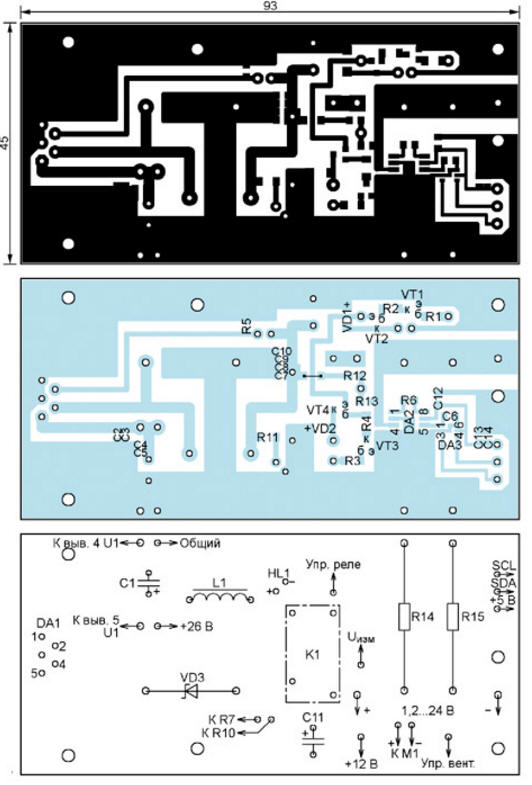
All operations for reading controlled parameters from their sensors, setting operating modes and displaying information on the HG1-HG3 indicators are performed by the DD4 PIC16F1827-I / SO microcontroller, whose clock frequency of 4 MHz is set by the RC generator built into it. The XP1 connector is intended for programming the microcontroller. After connecting to the 220 V network of the RS-50-24 (U1) power supply, its voltage is supplied to the adjustable switching voltage regulator on the DA1 LM2576T-ADJ chip and to the unregulated DA4 KR142EN8B stabilizer. With the help of the latter, a voltage of 12 V is obtained to power the coil of the relay K1 and the fan M1. Further, the integral stabilizer DA5 KR142EN5A lowers the voltage of +12 V to +5 V, necessary to power the rest of the unit. The switching regulator also includes a Schottky diode VD3, a storage inductor L1 and capacitors C7-C11. Its output voltage is regulated by variable resistors R7-R10. Their number is increased to achieve the desired smoothness of adjustment. The stabilized voltage is supplied to the load of the unit through the contacts of the relay K1.1. This is done so that you can turn off the load when the protection is triggered or, if necessary, turn it off without disconnecting the power wires from the unit. Regardless of the state of the contacts K1.1, part of the voltage from the output of the adjustable stabilizer through a voltage divider across resistors R12 and R13 is fed to the input of the ADC of the microcontroller DD4, is measured by it, and the voltage value at the output of the stabilizer is displayed on the indicator HG3. This allows you to set the desired voltage when the output is off, and only then, by pressing the SB3 button, send a command to close the contacts K1.1. When they are closed, pressing the same button opens them. After connecting the unit to the network and before pressing the SB3 button, the contacts are open. The load current sensor is a shunt connected to its negative wire. It is made up of resistors R14 and R15 connected in parallel. Shunt resistance - 0,05 Ohm. At a load current of 2 A, the voltage drops to 0,1 V on it. This is not enough to accurately measure the current, so the voltage from the sensor is amplified by the instrumental amplifier DA2 AD623ARZ [2], whose gain 11 is set by resistor R6. From the output of this amplifier, a voltage proportional to the load current is fed to the input of a 14-bit ADC DA3 ADS1100A0IDBVT [3], which has an internal amplifier for 2. Every second, the converter performs conversions, the results of ten of which are read by the microcontroller via the I interface2C. The use of an external ADC is due to the fact that the built-in ten-bit ADC of the microcontroller does not provide current measurement up to 2 A with the required accuracy. The temperature of the heat sink of the DA1 stabilizer is measured by the BK1 DS18B20 or DS18S20 sensor mounted on it. The microcontroller program determines the sensor type automatically. If the measured temperature exceeds the set value by 2 °C or more, then, at the command of the microcontroller, the M1 fan blowing the heat sink is turned on using transistors VT2 and VT1. The operation of the fan is signaled by the included decimal point after the least significant digit of the HG2 indicator. When the temperature is 2 °C lower than the set temperature, the fan and the decimal point on the indicator will be turned off. When the temperature sensor is missing or defective, the fan runs continuously, and two minuses are on on the HG2 indicator. The measured value of the output voltage of the unit is displayed on the three-digit indicator HG3 in volts with a decimal point before the lowest digit (tenths of a volt). The measured value of the load current is displayed on the three-digit indicator HG1. If it is less than 1 A, then it is displayed in milliamps, as evidenced by the extinguished decimal points in all digits. Current values equal to or greater than 1 A are displayed in amperes with a resolution of 0,01 A and a decimal point after the most significant digit (ampere units). The microcontroller controls all indicators statically through serial-to-parallel converters DD1-DD3, DD5-DD9. This allows you not to use interrupts in the microcontroller program that make it difficult to read information from the temperature sensor BK1 and ADC DA3. The anodes of all indicators are connected together. The voltage is supplied to them through a key on the transistor VT5, opened by variable duty cycle pulses generated by the microcontroller. This makes it possible to adjust the brightness of the indicators. When the protection is triggered, the relay contacts K1.1 open, and the dynamic head BA1, which is controlled by a key on the transistor VT6, beeps with a frequency of 1000 Hz and a duration of 0,5 s. Power supply U1 and integral stabilizers DA1, DA4, DA5 have their own built-in protection against output short circuit. The adjustable voltage regulator is assembled on a printed circuit board, which is shown in fig. 4. It contains all the elements shown in the diagram in fig. 1, except for the power supply U1 and switch SA1. There is one size 1206 surface mount jumper. Chip DA1 is equipped with a heat sink.
Integrated stabilizers DA4 and DA5 are located on the board, made in accordance with fig. 5. They are fixed from different sides on the same heat sink.
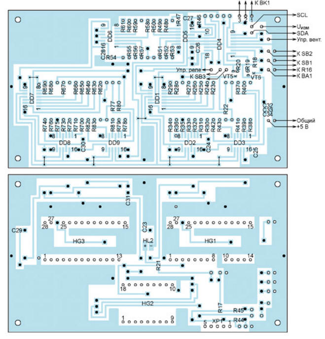
A drawing of the printed conductors of the control and indication board is shown in fig. 6, and the arrangement of elements on it - in Fig. 7. This board must have seven jumpers, similar to those mentioned above. Pins 9 and 26 of the HG1 indicator and pins 14 and 26 of the HG3 indicator are removed before being installed on the board. The dynamic head BA1 together with the resistor R16 is removed from the board. A selection of this resistor sets the desired volume of sound signals.
Outside the board are also variable resistors R7-R10. It is advisable to choose the maximum sizes, this will ensure the desired smoothness of voltage adjustment. Particular attention should be paid to the reliability of the contact between the engines of variable resistors and their resistive layers. Violations of this contact lead to surges in the output voltage of the unit, which can trigger the protection, but are nevertheless dangerous for the powered device. Resistors R1-R4, R11, R19, R20 - size 1206 for surface mounting, the rest - size 0805. R7-R10 choose the right size, but the ratings indicated on the diagram. Resistors R14 and R15 - KNP-500-5W-0R1-FP Oxide capacitors C1, C11 - aluminum with leads in one direction, C19, C22 - tantalum CTSMD-A. The remaining capacitors are 0805 ceramic surface mount capacitors. Microcircuits of the ADS1100 series are produced in several versions, differing in the address of the slave on the I bus2C, through which information is exchanged with the microcontroller. The address is indicated by two characters after the main part of the chip name, it cannot be changed. Only microcircuits with the address A0 (ADS1100A0) are suitable for use in the block under consideration. To use microcircuits with other addresses, a change in the microcontroller program is required. The design uses the relay OJ-SS-112LM12 [4]. It can be replaced by another with a 12 V winding and contacts capable of switching current up to 3 A at a constant voltage of 30 V. The appearance of the front panel of the power supply is shown in fig. 8. Here are the indicators HG1 (load current), HG2 (heat sink temperature), HG3 (output voltage), LED HL2, signaling the output is on, buttons SB1 (increase the parameter), SB2 (decrease the parameter) and two duplicate buttons SB3 (turning the output on and off).
To switch from the main voltage, current and temperature display mode to setting the voltage increase threshold, press the SB1 button, the HG1 and HG2 indicators will go out, and the threshold value will be displayed on the HG3 indicator. Each press of the SB1 button will increase, and the SB2 button will decrease it by 0,5 V. The threshold can be changed in the range from 2 to 25,5 V. Exit from this and subsequent modes to the main one occurs automatically if you do not press the SB1 and SB2 for 10 s. To switch from the main mode to setting the threshold for increasing the load current, briefly press the SB2 button. The indicators will go out, except for HG1, on which the threshold value will be displayed. By pressing the buttons SB1 and SB2 change it from 0,05 to 2 A in steps of 0,05 A. If, while in the main mode, you press and hold the SB2 button, then 1,5 s after switching on the current threshold setting mode, a cyclical selection of the five other parameters change modes with the same period will begin. You can do the same by pressing and holding the SB1 button, but in this case, the threshold setting mode for voltage will be activated first, then for current, and then the enumeration of other parameters will begin. When the indicators take on the form corresponding to the desired parameter, the held button should be released. In the mode of setting the allowable temperature of the heat sink, all indicators go out, except for HG2, which will display this value. By pressing the buttons SB1 and SB2 it can be changed in the range from 30 to 70 °C in steps of 1 °C. In the block voltmeter calibration mode, the HG1 indicator goes out, the HG2 indicator displays the calibration constant, and the HG3 indicator displays the value of the output voltage measured by the block. In this mode, connect an exemplary voltmeter to the output of the block, set the output voltage close to the maximum and, by selecting the calibration constant by pressing the buttons SB1 and SB2, achieve the coincidence of the readings of the HG3 indicator and the exemplary voltmeter. In the zero offset compensation mode of the instrumental amplifier DA3, the HG3 indicator goes out, the relay contacts K1. 1, the load is disconnected from the unit, the HG1 indicator displays the value of the compensated value, and the HG2 indicator displays the correction being made. By pressing the buttons SB1 and SB2, the readings of the indicators HG1 and HG2 must be equalized. The HG3 indicator is also off in the load current meter calibration mode, but at the moment this mode is turned on, a zero value is displayed on the HG1 indicator, since even in the previous mode, the load by the K1.1 relay contacts was disabled. A load is connected to the output of the block through an exemplary ammeter and, by pressing the SB3 button, a voltage is applied to it, which is set so that the load current is close to the maximum. By pressing the SB1 and SB2 buttons, the calibration constant displayed on the HG2 indicator is changed, achieving the same readings of the HG1 indicator and a reference ammeter. The last in the cycle is the mode for setting the brightness of the indicators. In this mode, all of them are enabled. The action of the buttons SB1 and SB2 in this case is opposite to other modes. By pressing the SB1 button, the brightness is reduced, and by SB2, the brightness is increased. All set parameter values are automatically stored in the non-volatile memory of the microcontroller; there is no need to re-enter them when the unit is turned on again. PCB files in Sprint Layout 5.0 format and the microcontroller program can be downloaded from ftp://ftp.radio.ru/pub/2014/10/blok.zip. Literature
Author: P. Kozhukhin
Machine for thinning flowers in gardens
02.05.2024 Advanced Infrared Microscope
02.05.2024 Air trap for insects
01.05.2024
▪ Human height and political preferences are interconnected ▪ Teleportation of quantum logic ▪ soy car
▪ section of the site Riddles for adults and children. Article selection ▪ article Fundamentals of harmonious coexistence of society and nature. Basics of safe life ▪ Article How many calories does a person need? Detailed answer ▪ article Repair of PHILIPS 6yr ECONOMY energy-saving lamps. HAM Tips ▪ article Power supply. Directory
Home page | Library | Articles | Website map | Site Reviews
www.diagram.com.ua |


 Leave your comment on this article: