|
|


 Arabic
 Bengali
 Chinese
 English
 French
 German
 Hebrew
 Hindi
Hindi Italian
 Japanese
 Korean
 Malay
Malay Polish
 Portuguese
 Spanish
 Turkish
 Ukrainian
 Vietnamese
|
ENCYCLOPEDIA OF RADIO ELECTRONICS AND ELECTRICAL ENGINEERING Pulse PSU - from the charger. Encyclopedia of radio electronics and electrical engineering
Encyclopedia of radio electronics and electrical engineering / Power Supplies Commercially available switching chargers for small equipment are a good basis for building power supplies that have more features than the original devices. How to turn such a charger into a power supply is described in the article. To charge rechargeable batteries and power compact equipment (mobile telephones, MP-3 players, electronic books), various pulse chargers are currently widely used. Unfortunately, their output voltage (usually about 5 V at a load current of 0,2 ... 2 A) is poorly filtered, has a high level of ripple, and they themselves are sources of radio interference, which does not allow them to be used to power radio receivers, sound amplifiers and measuring instruments. devices. However, all these shortcomings are quite easily eliminated, and after a simple refinement, such "chargers" become capable of feeding the named devices as well. As an example, the modification of the charger model AC-15E (its circuit is shown in Fig. 1), which provides an output stabilized voltage of 5,6 V at a load current of up to 0,8 A, is described below. The mains voltage of 220 V is supplied to the rectified voltage filter capacitor C5 through a protective resistor R1 and a diode D1 (the item designations of the elements correspond to those on the circuit board of the device). The pulse voltage converter is made on a high-voltage transistor Q1, a transformer T1 and elements R5, C6. Resistor R2 is designed to start the converter, elements D6, R9, C2 form a damping circuit.
Transistor Q2 has overload protection and output voltage stabilization units. As the emitter current of transistor Q1 increases, the voltage drop across resistor R3 increases, and when it becomes more than 0,6 V, transistor Q2 opens, which bypasses the emitter junction of Q1, after which the collector current of this transistor decreases. The output voltage stabilization unit works as follows. When the output voltage increases for any reason, the current through the emitting diode of the PC1 optocoupler increases, causing its phototransistor to turn on. Together with it, the transistor Q2 opens, which leads to a decrease in the base current of Q1 and a decrease in the voltage at the output of the device. When the output voltage deviates from the set value in the direction of decrease, the process proceeds in the opposite direction. Capacitor C7 filters the voltage of the winding III of the transformer T7 rectified by the Schottky diode D1. The output voltage of the device depends on the stabilization voltage of the zener diode D8 (it exceeds it by about 1,1 ... 1,2 V). The diagram of the power supply unit (PSU) assembled on the basis of this charger is shown in fig. 2 (position designations of new elements begin with the number 1). It was decided to make it for a stabilized output voltage of 3,3 V, for which the D8 zener diode was replaced by a device with a stabilization voltage of 2,4 V. A PSU with this output voltage can be used to power small radios, compact cameras, children's toys and other devices designed for for autonomous power supply with a voltage of 2,4 ... 3,7 V. If desired, using the appropriate zener diode, you can get an output voltage in the range of 3,3 ... 6 V.
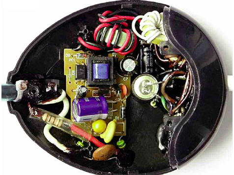
To reduce the interference generated by the pulse converter, it is connected to a 220 V network through an LC filter consisting of elements 1L1, 1L2, 1L3, 1C1, 1C2. The choke 1L3 is installed in place of the resistor R1, and instead of the latter, a protective resistor 1R1 of greater resistance is installed. The filter capacitor C5 has been replaced by a larger capacitor with a higher voltage rating. The value of the current-limiting resistor R5 (680 ohms) is reduced to 470 ohms, and the resistor R3 (10 ohms) is reduced to 5,1 ohms (the lower the resistance of this resistor, the greater the load current at which the protection is triggered). Significantly increased the capacitance of the filter capacitor C7. In parallel with the emitting diode of the optocoupler, the resistor R10, which was previously absent on the board, is connected (the lower its resistance, the higher the PSU output voltage). The voltage to the load is supplied through an LC filter, consisting of elements 1L4, 1L5, 1L6, 1C5-1C9. The 1HL1 LED lights up when there is an output voltage. The device is designed for long-term continuous operation at a load current of up to 0,5 A, but it is also capable of briefly supplying a load that consumes a current of 1 A. The operating mode in this case is as follows: 1 minute at a load current of 1 A, then a break of 5 minutes at a load current of less than 0,5 A, then again 1 min at a current of 1 A, and so on. The amplitude of ripple and noise at a load current of 0,5 A is about 50 mV, at 1 A it is about 100 mV (in this case, the output voltage drops to 3,1 V). An output current of 0,5 A at a voltage of 3,3 V is enough to power a portable radio containing a relatively powerful UMZCH, and a current of 1 A is enough to power portable cameras and most children's toys. PSU parts are mounted in a plastic case with dimensions of about 95x80x26 mm from the receiver for wireless computer keyboard and mouse (Fig. 3). Some additional parts are glued to the body with hot glue and polymer glue "Kvintol".
Resistor 1R1 - non-flammable R1-7 or imported discontinuous, placed inside an insulating silicone non-flammable tube. Capacitors 1C1, 1C2 - ceramic high-voltage, 1C3, 1C6, 1C7, 1C9 - ceramic multilayer (the first three are soldered between the terminals of the corresponding oxide capacitors, the fourth is mounted in the XS1 power plug). Oxide capacitors - imported analogues of K50-68. Inductors 1L1 - 1L3 - miniature industrial production with H-shaped ferrite magnetic cores and windings with a resistance of 3 ... wires. The greater the inductance of these chokes and the lower the resistance of their windings, the better. When reworking or repairing a faulty charger, instead of the MJE13001 transistor, you can use (taking into account the pinout) KF13001, MJE13002, MJE13003. If possible, it is desirable to choose an instance with the highest static base current transfer ratio and the lowest collector reverse current. Instead of the 2SC845 transistor, any of the 2SC1845, BC547, SS9014, KT645, KT3129, KT3130 series will do. The PS817C optocoupler can be replaced by any of the SFH617A-2, LTV817, PC817, EL817, PS2501-1, PC814, PC120, PC123, and the FR107 diode can be replaced by any of the UF4007, FR157, MUR160, 1N5398, KD247D, KD258G. The same diodes can replace 1N4007. Instead of a 1N4148 diode, any of 1N914, 1SS244, KD521, KD522 is suitable. Possible replacement of the Schottky diode 1N5819 - MBRS140TR, SB140, SB150, and the KIPD35E-Zh LED - any continuous glow without a built-in resistor. If the PSU is configured for a higher output voltage, then the resistance of the current-limiting resistor 1R3 must be increased. The appearance of the PSU is shown in Fig. 4.
To connect to the load, a two-wire cord with copper conductors with a cross section of 1 mm is used.2. Two ferrite tubular magnetic circuits 24 mm long are put on it: one is near the PSU case, the other is near the XS1 power plug. The case of the device is not shielded, so the simplest VHF radios powered by it (for example, assembled on K174XA34, K174XA34A, TDA7088T microcircuits) are sensitive to interference under conditions of uncertain radio reception if they are less than 500 mm away from it (approximately the same or greater RF level interfere with CFLs). If desired, it is not difficult to shield the PSU by pasting the case from the inside with sticky aluminum foil, electrically connected to the negative plate of the 1C8 capacitor. Other chargers can be upgraded in a similar way, for example, those assembled according to the schemes [1, 2]. Literature
Author: A. Butov
Machine for thinning flowers in gardens
02.05.2024 Advanced Infrared Microscope
02.05.2024 Air trap for insects
01.05.2024
▪ Visual stimuli amplify sound ▪ Impact of mobile phones on learning
▪ section of the Radio Control website. Article selection ▪ article The cat that walked by itself. Popular expression ▪ article How does a windmill work? Detailed answer ▪ article Hall Administrator (Maitre d'). Job description ▪ Article Magic Cucumber. Focus Secret
Home page | Library | Articles | Website map | Site Reviews
www.diagram.com.ua |


 Leave your comment on this article: