|
|


 Arabic
 Bengali
 Chinese
 English
 French
 German
 Hebrew
 Hindi
Hindi Italian
 Japanese
 Korean
 Malay
Malay Polish
 Portuguese
 Spanish
 Turkish
 Ukrainian
 Vietnamese
|
ENCYCLOPEDIA OF RADIO ELECTRONICS AND ELECTRICAL ENGINEERING Portable battery power supply. Encyclopedia of radio electronics and electrical engineering
Encyclopedia of radio electronics and electrical engineering / Chargers, batteries, galvanic cells At present, various compact devices powered by built-in batteries, such as mobile phones, multimedia pocket players, tablet computers, navigators, digital cameras, etc., are widely used. Due to the desire to reduce the size and weight of these devices, in most cases they are equipped with batteries of small capacity, which can cause inconvenience during their autonomous operation. To reduce the dependence of such devices on the capacity and condition of the built-in batteries, as well as the presence of a 230 V network, it is possible to manufacture the proposed device, from which it will be possible to power various radio equipment and charge the batteries built into it. The scheme of the device is shown in fig. 1. It is a power source with four Li-Ion 18650 batteries. The battery from a faulty netbook served as a donor for such batteries and a controller for them. It indicated the name - P22-900, capacity - 5800 mAh and nominal voltage - 7,2 V. The device provides a stabilized voltage of 5 or 6,2 V at the output at a load current of up to 1 A or an unstabilized 6 ... 8,4 .1,4 V at a current of up to 5 A. For a short time (less than 2 s every two minutes), the load current at any output voltage can be up to XNUMX A, this will allow you to connect a camera with a flash with a discharged internal power source.
The battery consists of four batteries G1-G4, which are connected to the controller A1 in pairs in parallel-series. The numbering of the controller outputs is conditional, it starts from the first negative output of the connector for connecting the battery to the netbook. In order to be able to power various devices from the battery and to recharge it, it is necessary to apply a logic low voltage to pin 5. To charge the battery, a constant voltage of 1 ... 12 V is applied to the input of the device (socket XS16). Diode VD1 serves to protect against reverse polarity of this voltage. A linear voltage regulator of 1 V is assembled on the integrated circuit DA9. From its output, the voltage through the current-limiting resistors R7, R8 and the diode VD5 is fed to the power outputs of the controller A1. Transistor VT1 opens when an external power source is connected to socket XS1, which turns on controller A1. Glowing LED HL1 signals the ongoing process of charging the battery. At a current of more than 50 mA, the transistor VT2 (germanium) opens and the HL1 LED shines with maximum brightness. When this LED stops glowing, the battery is charging. Capacitors C2-C4 and C6 are power-blocking DA1 microcircuits. The HL3 LED lights up when 9V is present. A 1A resettable fuse was found on the controller circuit board A5. Since the device was manufactured for lower current, an additional 1A resettable fuse F1,6 was installed to protect against damage. A voltage regulator of 78 and 05 V is assembled on the KA2R5 (DA6,2) microcircuit. This microcircuit is a controlled linear voltage regulator of positive polarity 5 V with an output current of up to 1 A, the maximum power dissipation is 15 W, the current consumption is about 10 mA. The microcircuit differs from conventional integrated stabilizers by a small minimum allowable voltage drop between the input and output, which does not exceed 1 V at a load current of 0,5 A. There is also an input (pin 4) for turning the stabilizer on and off. When the contacts of the SB1 button are closed, the output 5 of the controller A1 will have a low logic level, therefore, the battery voltage is present at the controller output (pins 7 and 8). In this case, a current of about 1 μA flows through the resistor R0,3. Through the closed contacts of the SB2.1 button, the battery voltage is supplied to the input of the voltage regulator 5 / 6,2 V. When the contacts of the SB3.1 button are closed, the output voltage is 5 V, when the contacts are open - 6,2 V, which is set by series-connected diodes VD2 and VD3. Resistors R4, R6 set the threshold voltage on / off the stabilizer. With the resistor values indicated in the diagram, this is a voltage of 6,3 V with closed contacts SB3.1 and 7,3 V with open contacts. Switching hysteresis - about 0,12 V. When the SB2 button contacts are in the lower position according to the diagram, power is supplied not to the DA2 voltage regulator, but to the XS2 socket. In this case, you can monitor the state of the battery and power various devices that do not require a stabilized voltage. The two-color LED HL2 shines green when the output voltage of the device is 6,2 V and red at 5 V. When the output voltage is 5 V, it goes to the output sockets XS2 and XS3 (USB connector). The output voltage of 5, 6,2 and 7,2 V is supplied to the socket XS2. Before giving a second life to a netbook lithium battery, its glued plastic case is carefully opened along the seam. If the batteries are discharged "to zero", they can be recharged directly for several minutes, bypassing the controller, with a current of 0,5 ... 1 A through a current-limiting resistor or from a current source. During this time, the batteries will gain enough voltage to turn on the controller. The measured capacity of a fully charged battery was about 5400 mAh when discharging with a current of 1 A, which is a good indicator for a battery that is about ten years old. The controller board (Fig. 2) was labeled BLA4AE00. The purpose of the wires is as follows. In the center are two blue ones - controller minus, green - control, two red ones - controller plus. Along the edges of the board: contact VC (blue wire) - minus elements G2 and G4, contact Vp (red wire) - plus elements Gl and G3, contact VM in the center (wire not soldered) - common elements G1-G4. The controller stops charging the battery when the voltage reaches 8,4 V. If you have another battery with a different controller at your disposal, you can find out the purpose of its outputs on the Internet or experimentally. If you use a laptop battery for an operating voltage of 10,8 V or 14,4 V, then due to the large difference between the input and output voltages, it is recommended to use a switching step-down voltage regulator in place of the DA2 stabilizer.
Before assembling the device, the batteries are disconnected from the controller. They are connected at the final stage of assembly and testing of the design, while you need to be careful - the short-circuit current of the leads of even a small-sized battery can reach tens of amperes. Some of the elements are placed on a circuit board with dimensions of 37x62 mm, and microcircuits are placed on a heat sink (Fig. 3). Installation - bilateral hinged. The AN78M09 chip can be replaced by the domestic KR142EN8A or any of the xxx78M09xx series. If you use the xxx78R09 series chip, the minimum input voltage of the device can be 10,5 V. The KA78R05 chip can be replaced by any of the xxx78R05 series in an isolated TO-220F-4L four-pin package. Both microcircuits are mounted on a common ribbed duralumin heat sink with a cooling surface area of 50 cm2 using heat-conducting paste KPT-8 or similar. In the case of the device, next to the heat sink, it is necessary to make several dozen ventilation holes. The connecting wires going to the pins of the microcircuits should be as short as possible.
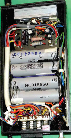
The 2SC3199 transistor can be replaced by any of the 2SC815, 2SC845, 2SC1815, 2SC9014, KT3102, KT6111 series, the SFT307 germanium transistor - with domestic ones from the MP25, MP26, MP39, MP40, MP41, MP42 series. The greater the current transfer ratio of the base of this transistor, the better. Diode SR504 can be replaced by diode SR505, SR506, SR306, SR360, 1N5822. Instead of a 1N5402 diode, any of the Sh540x, SRP300x, FR30x series will do. Diodes 1N4002 can be replaced by any of the Sh400x, RL10x series. Resistors - any appropriate power. Oxide capacitors - imported, C1 - ceramic or film for a rated voltage of at least 35 V. Capacitors C3, C4, C8, C9, C11 - ceramic for surface mounting, they are soldered directly to the power leads of the corresponding microcircuits or the leads of oxide capacitors. The remaining capacitors are ceramic K10-17. LED RL30-YG414S green glow and RL30-SR114S red can be replaced by any conventional low-power. The dual color LED L119SURKMGKWT can be replaced by any dual color common cathode LED from the L119 series. If the LED is with increased brightness, the resistance of the resistor R10 can be increased several times, which will reduce the current consumed by the device from the battery. Operating mode switch (buttons SB1-SB4) - a quadruple block of switches P2K with dependent fixation, two groups of switched contacts on each button. When you click on one of them, the rest return to their original position. Before assembling the structure, test such a switch, if necessary, clean its contacts from oxides. It is glued to the body of the device with hot glue and polymer glue "Kvintol". The battery cells are fixed in the case with a soft double-sided adhesive tape. The device is assembled in a plastic case measuring 28x91x175 mm. A view of the layout of nodes is shown in fig. 4. The mass of the assembled device is about 380 g. To power the device, you can use a 12 V car on-board network or another 12 ... 16 V voltage source, designed for a load current of at least 0,7 A. the load connected to the device will receive the supply voltage, regardless of the position of the contacts of the SB1 button.
The battery capacity of 5,8 Ah is enough to power, for example, the Okean-209 radio receiver for about 170 hours, operating at medium volume (100 mW), or for 60 ... 80 hours of powering a compact pocket MP3 player ( current consumption - 60 ... 80 mA), which is approximately ten times higher than the capabilities of the built-in battery. You can also fully charge the battery (capacity 800...1000 mAh) of the mobile phone several times. After using the device, do not forget to turn off its power and the loads connected to it by pressing the SB1 button. Author: A. Butov
Machine for thinning flowers in gardens
02.05.2024 Advanced Infrared Microscope
02.05.2024 Air trap for insects
01.05.2024
▪ Molecular memory works at room temperature ▪ Edible sensor for food freezing control
▪ section of the site Mobile communications. Article selection ▪ article Love the owner, love his dog. Popular expression ▪ article Which artist was the most prolific? Detailed answer ▪ article Airsleigh driver. Job description ▪ article DC Amplifier. Encyclopedia of radio electronics and electrical engineering ▪ article Disappearance of a vessel with water. Focus Secret
Home page | Library | Articles | Website map | Site Reviews
www.diagram.com.ua |


 Leave your comment on this article: