|
|


 Arabic
 Bengali
 Chinese
 English
 French
 German
 Hebrew
 Hindi
Hindi Italian
 Japanese
 Korean
 Malay
Malay Polish
 Portuguese
 Spanish
 Turkish
 Ukrainian
 Vietnamese
|
ENCYCLOPEDIA OF RADIO ELECTRONICS AND ELECTRICAL ENGINEERING Designs by M. Erofeev. Encyclopedia of radio electronics and electrical engineering
Encyclopedia of radio electronics and electrical engineering / Beginner radio amateur About the details of the set (Fig. 1)
Each part of the set is placed on a small bar corresponding to the dimensions of the element. Planks can be cut from getinax, textolite and even thick cardboard. The elements are attached to the strips with their leads (Fig. 1, a), to which the conductors are soldered from a stranded installation wire in insulation. The ends of the conductors are tinned and bent into a ring for a screw with a diameter of 3 mm. It is even better to solder the finished petals to the ends of the conductors. Transistors (Fig. 1,6). the relay (Fig. 1.c) and other parts can simply be glued. A graphic designation of the element is applied to the strips, indicating its type or denomination. Such a solution has didactic value - the parameters of all parts are visible on the slats, which are then placed on the circuit board according to the outline of the circuit diagram. Mounting plate (Fig. 2)
It can be made of any insulating material or plywood 2...3 mm thick and 200x300 (250x350) mm in size. On it, holes with a diameter of 5 mm are drilled in 6-3 rows, into which screws 20 mm long are inserted from below and fixed from above with nuts (it is advisable to lay washers between the nuts and the board). On the protruding ends of the screws during the installation of the device, the leads of the elements (no more than four) or the ends of the connecting conductors (they are included in the set) are placed and tightly tightened with a nut. An example of mounting a single-stage AF amplifier (Fig. 2, a) on a circuit board is shown in fig. 2b. The radio designer kit may include 2-3 such boards so that more complex devices can be assembled. And now let's get acquainted with some designs that are offered for assembly to beginner radio amateurs. Transistor and diode tester (fig. 3)
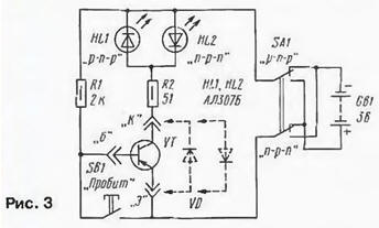
Before putting these parts into the assembled structure, you need to make sure that they have not failed after working in the previous device. The tester can be assembled as a separate unit or mounted on one of the circuit boards. If the transistor outputs are connected to sockets "E", "B". "K" is correct, and the moving contacts of switch SA1 are in the position corresponding to the structure of the transistor, one of the LEDs should light up. When you press the SB1 button, the LED will turn off. Other options for the reaction of the LED indicate a malfunction of the device - a breakdown of the transition or an open in the circuit of some output of the transistor. Diodes to be tested are included in sockets "K" and "E". The health of the diode will be signaled by the lit LED - HL1 or HL2, depending on the position of the switch contacts and the polarity of the diode leads. Sound "watchman" - tone generator (Fig. 4)
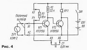
This design can serve as both a simple watchdog and a tone generator - an imitator of the sounds of an electric musical instrument (EMR). A generator is assembled on two transistors, which does not work until a serviceable security loop from a thin copper wire laid along the perimeter of the territory is connected to the terminals X1, X2. As soon as the integrity of the wire is broken, the generator will come into action, in the headphones (capsule type TA-56M with a resistance of 45-60 ohms) BF1 a sound will be heard, the tone of which depends on the ratings of the parts R1, C1. By connecting resistors up to 4 kOhm to the X510, X5 sockets, and to the X6 sockets. X0,1 capacitors with a capacity of up to XNUMX uF, you can change the tone of the sound over a wide range. If you pick up several resistors of different resistance and connect them to the X4, XXNUMX sockets through the buttons, we get the simplest EMP - by pressing the buttons, it’s easy to pick up some kind of melody. It is permissible to connect a reed switch instead of a loop to sockets X1, X2 or contacts installed, say, on the doors of protected premises (if there are several contacts, they are connected in series). Multivibrator - "flasher" (Fig. 5)
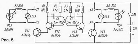
The basis of the device is a symmetrical multivibrator, made on transistors VT2, VT3. The pulse repetition rate of the multivibrator depends on the values of the resistors R2, R3 and capacitors C1, C2. The multivibrator pulses are fed to current amplifiers assembled on transistors VT1, VT4. In the collector circuit of each transistor (to terminals X1, X2 and X3, X4), it is permissible to include relatively powerful lamps HL1 and HL2 for a voltage of 6,3 V or two connected in series for a voltage of 3,5 V if a GB1 battery with a voltage of 6 V is used. with a source of a different voltage, the corresponding combinations of switching on the lamps are used. Instead of lamps, LEDs HL3, HL4 are suitable. One of the practical applications of such a multivibrator is a direction indicator for a bicycle. True, instead of a switch, you will have to install a switch with two sections of switching contacts and with the middle position of the control knob. In each of the extreme positions of the handle, one section will supply power to the device, and the second will turn on either one pair of signal lamps (right turn) or the other (left turn). DC amplifier (Fig. 6)
It is made on three transistors and has a high sensitivity. If you connect a photoresistor or a photodiode to its input terminals X1, X2 (the anode to the X2 terminal), the device will turn into a photorelay. When the photoresistor is illuminated with a flashlight beam or another light source, the transistors will open and the HLT lamp connected to the X4, XXNUMX terminals will light up. Replacing the input terminals with metal strips - contacts, we get a touch switch. By touching the contacts with your fingers, it will be possible to light the signal lamp. It is possible to use a photorelay to control a more powerful light source, say, a 12 V lighting lamp powered by a battery or mains rectifier. To do this, you will have to connect an electromagnetic relay K4 type RES1 passport RS10-4.529.031 or RES08 passport RS9-4.529.029 to the terminals XZ, X12. The closing contacts of the relay are connected in series with the load, in this case the lamp. Time relay (Fig. 7)
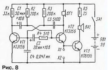
The capacitor timer can be used as a timer for photo printing. It provides exposure (turns on the EL1 lamp) from several seconds to several minutes, depending on the resistance of the resistors R I. R2 and the capacitance of the capacitor C1 (it can reach 2000 microfarads). After power is supplied by switch SA1, the transistors are closed, relays K1 and K2 are de-energized. The relay is ready to go. Pressing the SB1 button activates the relay K2. With contacts K2.1 it is self-locking (the button can be released), and contacts K2.2 supply voltage to the lamp EL1. The exposure countdown begins - the capacitor is charging through the resistors R1, R2. As soon as the voltage on it reaches a certain value, relay K1 will operate and, with its contacts K1.1, will disconnect the winding of relay K2 from the power source. Contacts K2.1 and K2.2 will return to their original position. The lamp turns off, the capacitor is discharged through the closed group of contacts K2.1 and the resistor R5. The time relay will go into standby mode. The shutter speed is set smoothly with a variable resistor R1. and abruptly - by connecting a resistor R2 and a capacitor C1 of other ratings. It is not difficult to calibrate the scale of a variable resistor using a stopwatch. Canary Trill Simulator (Fig. 8)
At one time, such a device was described in the magazine "Radio". But members of the Radioelectronics association slightly modified it by introducing capacitor C4 and adding a power amplifier based on a VT3 transistor, a dynamic head BA1 and a volume-limiting resistor R5 (it is made up of two 51 Ohm resistors connected in parallel). The sound of the simulator has become more pleasant. If clamps X1 and X2 are closed, trills will be heard only in the telephone capsule BF1 (type TA-56M). When these clamps are open, a louder sound will be heard from the BA1 dynamic head (any head with a power of 0,25-1 W with a voice coil with a resistance of 8-10 Ohms). In this version, the simulator is able to play the role of a home bell, if you connect an external bell button to it instead of a switch. By selecting elements C1 - C3, R4, you can change the tone of sound, the duration of trills and pauses between them. Simulator sounds "meow" (Fig. 9)
This simulator is capable of making sounds reminiscent of a kitten meowing. Thanks to the introduced R3C2 chain, the sound becomes more natural. If you want to experiment with the simulator, it is recommended to install parts C1, C3, R2, R4 of different denominations. Universal simulator (Fig. 10)
It is developed on the basis of a two-tone siren and consists of a "slow" (with a low pulse repetition rate) multivibrator, made on transistors VT1, VT2, sound (transistors VT3, VT4), as well as a power amplifier on a transistor VT5. Chain R5C3 - integrating, allowing you to smoothly change the frequency of the second multivibrator. With the ratings of capacitors C1 - 10 uF. C2 - 20 uF, C3 - 200 uF, C4 and C5 - 0.01 uF and the connections shown in the diagram, the simulator provides the sound of an alarm siren. However, if you change the value of capacitors C1, C2 from 0.5 to 100 uF, C3 - from 20 to 500 uF. C4, C5 - from 0.01 to 0.5 uF and rearrange the conductors from the top resistors R7 according to the terminal diagram. R8 to terminals X1. X4, X5, X8, X11, X14 in different combinations, you will be able to get dozens of different (sometimes very unusual) sounds. These are bird trills, the noise of a motorcycle, the sound of "tremolo", "snoring" and many others. The sound can be even more diversified if you change the supply voltage within 2 ... 9 V. When carrying out these experiments, it is desirable to connect an oscilloscope to the specified terminals in order to observe the change in the shape of the oscillations. Author: M.Erofeev
Artificial leather for touch emulation
15.04.2024 Petgugu Global cat litter
15.04.2024 The attractiveness of caring men
14.04.2024
▪ Navigation system for firefighters ▪ Indium shortage threatens touch screen manufacturing ▪ 100 volt voltage regulator LM5008
▪ section of the site Data transfer. Article selection ▪ article by Xun Tzu. Famous aphorisms ▪ article How did you find the locator in bats? Detailed answer ▪ article Prickly bristle ciliate. Legends, cultivation, methods of application ▪ article Consumer electronics. Power regulators, thermometers, heat stabilizers. Directory ▪ article Magic Wallet. Focus Secret
Home page | Library | Articles | Website map | Site Reviews
www.diagram.com.ua |


 Leave your comment on this article: