|
|


 Arabic
 Bengali
 Chinese
 English
 French
 German
 Hebrew
 Hindi
Hindi Italian
 Japanese
 Korean
 Malay
Malay Polish
 Portuguese
 Spanish
 Turkish
 Ukrainian
 Vietnamese
|
ENCYCLOPEDIA OF RADIO ELECTRONICS AND ELECTRICAL ENGINEERING Battery charge limiter indicator. Encyclopedia of radio electronics and electrical engineering
Encyclopedia of radio electronics and electrical engineering / Power Supplies When charging several AA or AAA Ni-Cd or Ni-Mh batteries connected in series at the same time, a situation often arises when some of them have not yet been charged, while others are already being recharged. This is due to the fact that the actual capacity of the batteries, especially if they are "not the first freshness", can differ significantly from the nominal one, and when charging with one current, some of them charge faster than others. To eliminate this situation, you can assemble a limiter indicator, which is connected in parallel to each battery. The device is intended for installation in simple chargers, in which charging is carried out with a stable current and there is no control of the voltage of each battery or charging time. The scheme of the device is shown in fig. 1. It is a step-up voltage converter loaded with an LED, and is assembled on a specialized NCP1400ASN33T1 (NCP1400ASN50T1) microcircuit. The limiter indicator, connected in parallel with the G1 battery being charged, practically does not consume current until the battery voltage is less than 1,42 V. Therefore, the entire charging current "goes into action", i.e., charges the battery. When the voltage exceeds the above value, the converter turns on, the current consumed by it increases, and the charging current decreases significantly, down to zero. The LED starts to glow, signaling the end of battery charging.
The Zener diode VD1 protects the converter from overvoltage, which may appear if the battery is not installed, failed, or due to poor contact in the holder. The converter turns on if the voltage at the control input CE exceeds 0,5 ... 0,6 V. It enters this input through the diodes VD2 and VD3, and its value will be less than the voltage drop across them. The current through these diodes, and hence the voltage across them, sets the resistor R1, and by selecting it, you can set the threshold for turning on the voltage converter. In this case, the threshold voltage is set to 1,42 V. The current consumed by the converter exceeds the current flowing through the LED by 2,5...3 times. If you use a white LED, at a voltage of 3,3 V, the current through it will depend mainly on its type and may need to be selected. If, for example, an LED draws 20 mA, the converter will draw about 50 mA. It is by this value that the charging current will decrease after the converter is turned on. To set the desired current consumption, it is necessary to use a green or yellow LED by connecting resistor R2 in series with it. A selection of this resistor sets the current consumed by the entire converter. You can use a red LED, but first you need to check that it does not shine at a voltage of 1,4 V, some specimens are capable of this. If you use small-sized elements for surface mounting, the printed circuit board of the device will be small. Its drawing is shown in Fig. 2. It is double-sided. Through the holes in the board, the pads are interconnected on both sides. The LED, capacitor and resistor R2 are installed on one side, the rest of the elements are on the other. Diodes CDLL4148 can be replaced by output diodes of the KD521 and KD522 series. The zener diode is low-power for a stabilization voltage of 3 ... 3,3 V. Resistors and a capacitor are for surface mounting, size 0805 or 1206. The inductor must be rated for a current of 200 ... 250 mA, chokes are suitable - LQY4N, LQN4N, SDR0703, or output series EC24. The LED can be any, and since the current through it is quite large, the use of an LED of increased brightness is not necessary.
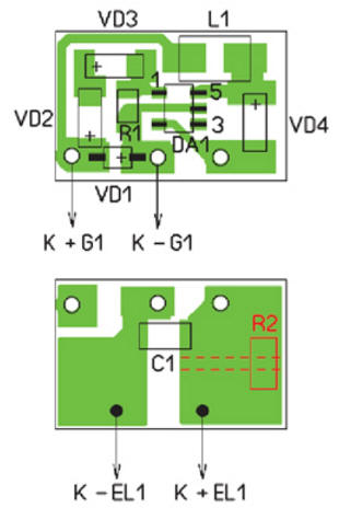
The placement of elements on the board is shown in fig. 3. An additional resistor R2 is installed from the installation side of the LED, having previously made a cut in the printed conductor. The cut and resistor R2 are highlighted in fig. 3 in red. The appearance of the device is shown in fig. 4.
It is convenient to install such a limiter indicator in a charger with a charging current of 60 ... 80 mA (for batteries with a capacity of up to 800 mAh). In this case, after turning on the LED, the battery will continue to be recharged with several times less current. To increase the current consumed by the converter, it is necessary to install two or three LEDs at its output, each with its own resistor. If the charging current in the charger is 150 ... 200 mA (for batteries with a capacity of up to 1,5.2 Ah), you should use a microcircuit with an output voltage of 5 V (NCP1400ASN50T1) and install a current-limiting resistor in series with the LED (all changes for this case are highlighted on Fig. 1 in red). By selecting this resistor, you can set the desired LED current. In this case, the current consumed by the converter will be approximately four times greater. You may need to use a more powerful LED or install one or two more LEDs in parallel, each with its own current-limiting resistor. It should be noted that the current pulse through the inductor can reach 400 mA, so it must be rated for this current. It should be noted that the turn-off voltage of the converter is less than the turn-on voltage by about 0,1 V. If the battery is slightly discharged after turning on the converter, the converter will turn off and charging will continue. Establishment comes down to a selection of resistors. A voltage of 1,42 V is applied to the device and a selection of resistor R1 is used to turn on the converter. The resistance of this resistor should not be more than 200 kOhm, if it turns out more, it is necessary to select other diodes VD2 and VD3. The turn-on threshold is controlled several times by applying a voltage of 1,2 V to the converter and gradually increasing it to 1,5 V. If necessary, the adjustment is repeated. How to change the current consumed by the converter, it was said above. Author: I. Nechaev
Machine for thinning flowers in gardens
02.05.2024 Advanced Infrared Microscope
02.05.2024 Air trap for insects
01.05.2024
▪ Beam of cold atoms without laser cooling ▪ IR receiver modules TSOP48xxxxAM ▪ There is a direct link between hunger and pain ▪ Diamond detectors to search for dark matter
▪ site section Parameters, analogues, marking of radio components. Article selection ▪ article by Eugene Ionesco. Famous aphorisms ▪ article In which state did a third-order enclave exist? Detailed answer ▪ article Agave furcroid. Legends, cultivation, methods of application ▪ article Electronic hourglass. Encyclopedia of radio electronics and electrical engineering
Home page | Library | Articles | Website map | Site Reviews
www.diagram.com.ua |


 Leave your comment on this article: