|
|


 Arabic
 Bengali
 Chinese
 English
 French
 German
 Hebrew
 Hindi
Hindi Italian
 Japanese
 Korean
 Malay
Malay Polish
 Portuguese
 Spanish
 Turkish
 Ukrainian
 Vietnamese
|
ENCYCLOPEDIA OF RADIO ELECTRONICS AND ELECTRICAL ENGINEERING Switching power supply, 220/5 volts 2,5 amperes. Encyclopedia of radio electronics and electrical engineering
Encyclopedia of radio electronics and electrical engineering / Power Supplies Power supplies with transformers for a frequency of 50 Hz today have practically lost their positions to pulse power supplies with a high operating frequency, which, with the same output power, usually have smaller dimensions and weight, and higher efficiency. The main limiting factors for self-manufacturing of switching power supplies by radio amateurs are the difficulties in calculating, manufacturing or purchasing a ready-made pulse transformer or a ferrite magnetic circuit for it. But if you use a ready-made transformer from an ATX form factor computer power supply to assemble a low-power switching power supply, the task is greatly simplified. I happened to have a defective IW-ISP300J2-0 (ATX12V300WP4) computer power supply. It had a jammed fan, a broken low-power Schottky diode, and more than half of all installed oxide capacitors were swollen and lost capacity. However, the standby voltage at the output was + 5VSB. Therefore, it was decided, using a pulse transformer of the standby voltage source and some other details, to make another switching power supply with an output voltage of 5 V at a load current of up to 2,5 A. In the ATX power supply, the standby voltage source nodes are easy to isolate. It gives a voltage of 5 V and is designed for a maximum load current of 2 A or more. True, in old power supplies of this type, it can be rated for a current of only 0,5 A. If there is no explanatory inscription on the block label, you can be guided by the fact that the standby voltage source transformer with a maximum load current of 0,5 A is much smaller than the source transformer by 2 A. A diagram of a home-made switching power supply with an output voltage of 5 ... 5,25 V at a maximum load current of 2,5 A is shown in fig. 1. Its generator part is built on transistors VT1, VT2 and a pulse transformer T1 in the image and likeness of the one in the computer unit from which the transformer was removed.
It was decided not to repeat the secondary nodes of the original power supply (after the +5 V voltage rectifier), but to assemble them according to the traditional scheme with an integrated parallel voltage regulator as a node for comparing the output voltage with the exemplary one. The input mains filter is assembled from existing parts, taking into account the free space for their installation. The alternating mains voltage of 230 V through the fuse-link FU1 and the closed contacts of the SA1 switch enters the RLC filter R1C1L1L2C2, which not only protects the unit from interference from the mains, but also prevents the interference generated by the impulse unit itself from penetrating into the network. Resistor R1 and chokes L1, L2, in addition, reduce the surge of current consumed when the unit is turned on. After the filter, the mains voltage is supplied to the bridge diode rectifier VD1-VD4. Capacitor C9 smooths out the ripple of the rectified voltage. On a high-voltage field-effect transistor VT2, a generator assembly of a voltage converter is assembled. Resistors R2-R4 are designed to start the generator. The total power of these resistors is increased, since the printed circuit board of the power supply from which they are removed has noticeably darkened under them as a result of overheating. For the same reason, the damping resistor R8 is set to a higher power, and a more powerful diode than in the prototype is used as VD6. Zener diode VD5 protects the field-effect transistor VT2 from exceeding the allowable voltage between the gate and source. On the bipolar transistor VT1, an overload protection unit and output voltage stabilization are assembled. With an increase in the source current of the transistor VT2 to 0,6 A, the voltage drop across the resistor R5 will reach 0,6 V. The transistor VT1 will open. As a result, the voltage between the gate and the source of the field-effect transistor VT2 will decrease. This will prevent further increase in current in the drain-source channel of the FET. Compared with the prototype, the resistance of the resistor R5 is reduced from 1,3 to 1,03 ohms, the resistor R6 is increased from 20 to 68 ohms, the capacitance of the capacitor C13 is increased from 10 to 22 microfarads. The voltage from the winding II of the transformer T1 is supplied to the rectifier Schottky diode VD8, the voltage swing at the terminals of which is about 26 V. The ripple of the rectified voltage is smoothed out by the capacitor C15. If, for one reason or another, the output voltage of the power supply tends to increase, the voltage at the control input of the parallel voltage regulator DA1 rises. The current flowing through the emitting diode of the optocoupler U1 increases, its phototransistor opens. The transistor VT1, which opens as a result, reduces the voltage between the gate and the source of the field-effect transistor VT2, which returns the output voltage of the rectifier to the nominal value. A circuit of resistor R16 and capacitor C16 prevents the stabilizer from self-exciting. The manufactured power supply is equipped with a pointer load current meter PA1, which greatly increases the usability of it, since it allows you to quickly assess the current consumed by the load. The shunt for the microammeter PA1 is the ohmic resistance of the inductor winding L4. LEDs HL1 and HL2 illuminate the microammeter scale. Voltage is supplied to the output connectors XP2 and XS1 through the filter L5C19. The VD9 zener diode with the VD10 diode prevents an excessive increase in the output voltage in the event of a malfunction in its stabilization circuits. The operating frequency of the converter is about 60 kHz. At a load current of 2,3 A, the amplitude of the rectified voltage ripple on the capacitor C15 is about 100 mV, on the capacitor C18 it is about 40 mV, and at the output of the power supply it is about 24 mV. These are very good indicators. The efficiency of the power supply at a load current of 2,5 A - 71%, 2 A - 80%, 1 A - 74%, 0,2 A - 38%. The output short-circuit current is about 5 A, while the power consumed from the network is about 7 W. Without load, the unit consumes about 1 watt from the network. Measurements of power consumption and efficiency were carried out when the unit was powered by a constant voltage equal to the amplitude of the mains. During prolonged operation with a maximum load current, the temperature inside its case reached 40 оC at ambient temperature 24 оC. This is significantly less than the numerous small-sized switching power supplies included in various consumer electronics kits. At a load current equal to half of the declared maximum value, they overheat by 35 ... 55 оC. Most of the details of the described power supply are installed on a 75x75 mm board. Installation - bilateral hinged. A plastic junction box with dimensions of 85x85x42 mm is used as a housing for external wiring. The block in an open case is shown in fig. 2, and its appearance is shown in Fig. 3.
In the manufacture of the unit, special attention should be paid to the phasing of the windings of the transformer T1, the beginning and end of none of them should be mixed up. The applied transformer 3PMT10053000 (from the computer power supply mentioned above) also has a winding intended for the -12 V voltage rectifier, which is not used in this case. Instead, you can use almost any similar transformer. For orientation when choosing a transformer, I give the values \u2,4b\u17bof the inductance of the windings used: I - 55 mH, II - XNUMX μH, III - XNUMX μH. As PA1, an M68501 microammeter (a level indicator from a domestic tape recorder) was used. Please note that microammeters of this type of different years of production have a very large variation in the resistance of the measuring mechanism. If it is not possible to set the desired measurement limit by selecting the resistor R13, you need to connect a small resistance wire resistor (approximately 4 Ohm) in series with the L0,1 inductor. When calibrating the microammeter, it unexpectedly turned out that it is very sensitive to static electricity. The raised plastic ruler could deflect the instrument needle to the middle of the scale, where it could remain even after the ruler was removed. This phenomenon was eliminated by removing the existing film scale. Instead, sticky aluminum foil was glued, which also covered the free sections of the case. The foil shield should be connected with a wire to any terminal of the microammeter. You can try to treat the body of the microammeter with an antistatic agent. The paper scale printed on the printer is glued in place of the removed one. A sample scale is shown in fig. 4. As you can see, in this microammeter it is noticeably non-linear.
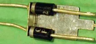
Resistor R1 - imported non-flammable. Instead of such a resistor, you can install a wire with a power of 1 ... 2 W. Domestic metal-film and carbon resistors are not suitable as R1. The remaining resistors for general use (C1-14, C2-14, C2-33, C1-4, MLT, RPM). The surface mount resistor R19 is soldered directly to the pins of the XS1 socket. Oxide capacitors - imported analogues of K50-68. The use of capacitors C15, C18, C19 with a nominal voltage of 10 V instead of 6,3 V oxide capacitors often used in switching power supplies significantly increases the reliability of the device. Film capacitor C2 with a capacity of 0,033 ... 0,1 μF is designed to operate at an alternating voltage of 275 V. The rest of the capacitors are imported ceramic. Capacitors C14, C17 are soldered between the terminals of the respective oxide capacitors. Capacitor C20 is installed inside the XP2 plug. Powerful assembly of S30D40C Schottky diodes taken from a faulty computer power supply. In the device under consideration, it can work without a heat sink. You can replace it with MBR3045PT, MBR4045PT, MBR3045WT, MBR4045WT. At maximum load current, the case of this assembly heats up to 60 оC is the hottest element in the device. Instead of a diode assembly, you can use two conventional diodes in a DO-201AD package, for example, MBR350, SR360, 1N5822, connecting them in parallel. To them, from the side of the cathode leads, an additional copper heat sink, shown in Fig. 5.
Instead of 1N4005 diodes, 1 N4006, 1 N4007, UF4007, 1N4937, FR107, KD247G, KD209B are suitable. Diode FR157 can be replaced by FR207, FM207, FR307, PR3007. One of the listed diodes is also suitable instead of KD226B. Any of the UF103, UF4003, 4004N1GP RG4935D, EGP2C, KD20B can serve as a replacement for the FR247 diode. Instead of the BZV55C18 zener diode, 1N4746A, TZMC-18 will do. LEDs HL1, HL2 - white glow from the LCD backlight unit of a cell phone. They are glued to the microammeter with cyanoacrylate glue. The KSP2222 transistor can be replaced by any of the PN2222, 2N2222, KN2222, SS9013, SS9014, 2SC815, BC547, or KT645 series, subject to differences in pin assignments. FET SSS2N60B removed from the failed power supply and installed on a finned aluminum heat sink with a cooling surface area of 20 cm2, and all transistor outputs must be electrically isolated from the heat sink, when the power supply is operating with a maximum load current, this transistor heats up to only 40 оC. Instead of the transistor SSS2N60B, you can use SSS7N60B, SSS6N60A, SSP10N60B, P5NK60ZF, IRFBIC40, FQPF10N60C. The EL817 optocoupler can be replaced with another four-pin optocoupler (SFH617A-2, LTV817, PC817, PS817S, PS2501-1, PC814, PC120, PC123). Instead of the LM431ACZ chip, any functionally similar one in the TO-92 package (TL431, AZ431, AN1431T) will do. All chokes are of industrial production, and the magnetic circuits of the chokes L1, L2, L4 are H-shaped ferrite. The resistance of the inductor winding L4 is 0,042 ohms. The larger this inductor in size, the less its winding will heat up, the more accurately the PA1 microammeter will measure the load current. Inductor L5 is wound on an annular magnetic circuit, the lower the resistance of its winding and the greater its inductance, the better. Inductor L3 - a ferrite tube 8 mm long put on the output of the common cathode of the VD5 diode assembly. The XP2 plug is connected to the C19 capacitor with a double stranded wire 2x2,5 mm2 120 cm long. The XS1 USB-AF socket is fixed in the hole in the device housing with adhesive. The first inclusion of the manufactured device in the AC mains is carried out without load through an incandescent lamp with a power of 40 ... 60 W at 235 V, installed instead of the FU1 fuse-link. Preliminary load tests are carried out by replacing FU1 with an incandescent lamp with a power of 250 ... 300 W. The filaments of incandescent lamps should not glow during normal operation of the power supply. Unmistakably made from serviceable parts, the device starts working immediately. If necessary, by selecting the resistor R13, you can set the ammeter readings. Selecting resistor R14, set the output voltage of the power supply to 5 ... 5,25 V. The increased voltage compensates for its drop on the wires connecting the unit to the load. The manufactured power supply can be used in conjunction with a modified USB hub [1], to which you can connect up to four external 2,5-inch hard drives operating simultaneously. The power will be enough to power, for example, devices such as [2]. Literature
Author: A. Butov
Machine for thinning flowers in gardens
02.05.2024 Advanced Infrared Microscope
02.05.2024 Air trap for insects
01.05.2024
▪ To save nature, nature reserves will have to be closed. ▪ TPS62510 - 1,5A Buck Converter for Portable Devices ▪ Trypillians ate almost no meat ▪ Developed a chip that can withstand the cold of space
▪ site section Power regulators, thermometers, heat stabilizers. Article selection ▪ Alphonse article. Popular expression ▪ article Why is fire hot? Detailed answer ▪ article Electronic ignition: options. Encyclopedia of radio electronics and electrical engineering ▪ article Guessing points on dice. Focus Secret
Home page | Library | Articles | Website map | Site Reviews
www.diagram.com.ua |


 Leave your comment on this article: