|
|


 Arabic
 Bengali
 Chinese
 English
 French
 German
 Hebrew
 Hindi
Hindi Italian
 Japanese
 Korean
 Malay
Malay Polish
 Portuguese
 Spanish
 Turkish
 Ukrainian
 Vietnamese
|
ENCYCLOPEDIA OF RADIO ELECTRONICS AND ELECTRICAL ENGINEERING Repair and modification of chargers Sonar UZ 205. Encyclopedia of radio electronics and electrical engineering
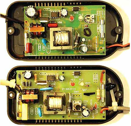
Encyclopedia of radio electronics and electrical engineering / Chargers, batteries, galvanic cells The compact charger (CH) "Sonar UZ 205.07" manufactured by PF SONAR LLC is designed for charging sealed lead-acid batteries with a nominal voltage of 12 V with a capacity of up to 15 Ah. While charging a 7 Ah battery operated in conjunction with an echo sounder, the charger hissed and smoked. Considering its relatively high cost, it was decided to try to repair it. On fig. 1 below shows a view of the installation of this charger after repair and refinement, and at the top - a similar charger "Sonar UZ 205.01" as is, i.e., in the state of delivery. Checking the details of the smoked memory revealed two reasons for the malfunction of the device. The first is a burnt film capacitor C10 (0,01 uF, 630 V), which is installed in the damping circuit of the primary winding of the pulse transformer T1. Usually, a ceramic capacitor with a rated voltage of 1000 or 2000 V is used in this place. It was considered expedient to do so in this case: instead of a faulty film capacitor, a ceramic capacitor of the same capacity, but with a rated voltage of 2000 V, was installed.
The second reason is a malfunction of the HER107S diode (VD6), which, with a voltage on the ohmmeter probes of 0,3 V, “ringed” in both directions as a resistor with a resistance of about 1 kOhm. Instead of the faulty one, a "real" HER107 diode was installed, for the thicker leads of which the holes in the printed circuit board had to be drilled. In the absence of such a diode, you can install, for example, UF4007. After the restoration of the memory, it was decided to eliminate the obvious, in the opinion of the author, the shortcomings of this product: 1. The printed circuit board on the side of the connections was not washed from the soldering flux: it was spattered, smeared not only between the contacts, printed tracks, but also resistors and capacitors for surface mounting were flooded, including in high-voltage circuits, which can lead to only to a violation of the operating modes of the device, but also to spontaneous combustion of the circuit board. 2. The mains power cable and the wire for connecting to the battery were soldered directly to the contact pads of the printed conductors (the holes provided for them in the board were not used, which can be clearly seen in the top photo of Fig. 1), while these wires are not attached to the memory case. fastened, ready to come off at any moment along with printed conductors. When finalizing, both wires were passed through the holes intended for them in the board and only then soldered to the corresponding contact pads. There was another defect in the installation of the power cord: the distance between the contacts for soldering the power wires was only 2 mm, which was fraught with a great danger of self-ignition of the board. To prevent this from happening, one of the network wires was soldered in such a way that the minimum distance between the network contacts increased to 7 mm (for this, the F1 fusible insert had to be raised above the board, and the excess part of the printed conductor removed). Finally, plastic tubes are put on both pairs of wires (network and going to the battery), after which they are securely fixed in the case, as shown in the bottom photo of Fig. 1. And further. To connect the charger to a 230 V network, the manufacturer used a wire of very low quality, therefore, if possible, it is advisable to replace it. 3. The film capacitor C3 (0,1 uF, 400 V) included in the mains LC filter turned out to be the same type as C10. Such capacitors, installed in 230 V AC 50 Hz voltage circuits, are often damaged, so it was replaced by a film capacitor of the same capacity with a rated AC voltage of 275 V, specially designed for operation in AC circuits (Fig. 2).
4. Oxide capacitor C4 with a capacity of 10 μF, filtering the voltage rectified by the diode bridge VD1-VD4, had a rated voltage of only 350 V, while the amplitude of the mains voltage (according to GOST - 230 V), taking into account the permissible deviation upwards by 10%, can reach 357 V. The lack of a voltage margin often leads to various pyrotechnic effects. To prevent this from happening, capacitor C4 was replaced with the same capacitance, but with a rated voltage of 400 V. 5. The ceramic capacitor C11 (1000 pF, 2000 V), connected between the primary and secondary windings of the pulse transformer, did not inspire confidence - very thin, there are no "certification" inscriptions. The safety of using the device depends on the quality of this capacitor, since during its breakdown the secondary low-voltage part of the charger will be under the mains voltage of 230 V. It was replaced by a ceramic one of the same capacity and with the same rated voltage, but with a volume approximately four times larger. 6. The pulse transformer is made carelessly. The ferrite magnetic core dangled freely in the coil frame. The defect was eliminated by gluing the magnetic circuit to the frame with instant cyanoacrylic glue. In the second memory (upper photo in Fig. 1), the magnetic core of the transformer was glued with a large skew and also not fixed in the coil and not wrapped with "traditional" Chinese yellow tape. In addition, this magnetic circuit made of conductive ferrite on one side was in contact with the output of the Schottky diode VD8, and the other "rubbed" against the film capacitor C10 that burned out in the first memory. If in the second memory C10 had time to burn out, then the mains voltage could get into the secondary circuit. 7. The high-voltage transistor Q4ESN50A (VT1) when charging the battery heated up to 90 ° C with the case cover removed. This situation is, in principle, tolerable, however, to increase the reliability, a 40x10x2 mm plate-like duralumin heat sink was screwed to it (not shown in Fig. 1). The temperature of the transistor case dropped to about 75 оC at room temperature 28 оC. Such a high heating of the high-voltage transistor hints at the poor quality of the ferrite of the pulse transformer, which, by the way, also heats up very much. 8. The very hot C12 oxide capacitor (470uF, 16V) installed in the 14,5V rectified voltage filter was replaced by a 1000uF capacitor with a nominal voltage of 25V, which remained almost cold during operation. The defect was noticed by chance already at the time of assembling the case - "something" burned the fingers. The leakage current of the old capacitor reached 0,3 A at a voltage of 10 V and 2,5 A at a voltage of 18 V on the plates. 9. The implementation of protection against "reverse polarity" did not inspire confidence, therefore, in order to exclude polarity reversal of connecting the charger to the battery, and it to the echo sounder, all terminal connectors were replaced: the charger and echo sounder were equipped with standard round plugs with an outer diameter of 5,5 mm, and battery - reciprocal sockets for such plugs.
Replaced parts are shown in fig. 3 (the first on the left is a burned-out film capacitor C10, the second is a thin ceramic C11, the third is a VD6 diode, the fourth is a capacitor C3). Author: A. Butov
Machine for thinning flowers in gardens
02.05.2024 Advanced Infrared Microscope
02.05.2024 Air trap for insects
01.05.2024
▪ Connecting chips with an inkjet printer and silver ink ▪ Synthetic wood is not afraid of fire ▪ New 32-bit TMP92CZ26XBG processor ▪ Mars changes the structure of near-Earth asteroids
▪ site section Acoustic systems. Article selection ▪ article Foreign economic activity. Crib ▪ article How do spiders use the power of electricity to trap prey? Detailed answer ▪ article Paraglider Alpha-29. Personal transport ▪ article Amazing vase. Focus secret
Home page | Library | Articles | Website map | Site Reviews
www.diagram.com.ua |


 Leave your comment on this article: