|
|


 Arabic
 Bengali
 Chinese
 English
 French
 German
 Hebrew
 Hindi
Hindi Italian
 Japanese
 Korean
 Malay
Malay Polish
 Portuguese
 Spanish
 Turkish
 Ukrainian
 Vietnamese
|
ENCYCLOPEDIA OF RADIO ELECTRONICS AND ELECTRICAL ENGINEERING Repair switching power supply PC202003040. Encyclopedia of radio electronics and electrical engineering
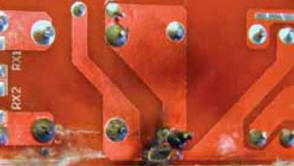
Encyclopedia of radio electronics and electrical engineering / Power Supplies The compact switching power supply model PC202003040 LED STRIP PS 40 W is designed to operate with a load of up to 40 W at an output voltage of 12 V DC. After working for several days with a load of about 15 W, the unit began to smoke and stopped working. Since the cost of this product is lower than the retail price of the main parts included in it and less than the cost of a trip to the store, it was decided not to take it in for repair under warranty, but try to do it yourself. After disassembling the device, the main malfunction did not have to be looked for for a long time. On fig. 1 it can be seen that a breakdown occurred on the block board between the printed conductors under the mains voltage of 230 V AC. Part of the printed track burned out, while the F1 fuse survived (this is a common malfunction in products with mains power with such design flaws). The distance between the indicated tracks was only about 1 mm, while for reliable operation of the device it must be at least 5 mm, and even in this case it would not be superfluous to have a through cut in the printed circuit board material between the tracks.
To restore the unit's operability, the printed tracks leading from the two-winding choke LF1 (see also a fragment of the circuit in Fig. 2) to the diodes D3, D4 and the ceramic capacitor CY2 were removed, and the corresponding connections were made with a mounting wire in PVC insulation (Fig. 3 ).
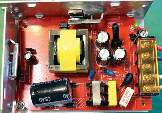
In order to improve the reliability of the device, several improvements were made. So, with the help of a hand cutter, the distance between the contact pad for the drain terminal of the high-voltage transistor Q2,5 and the printed conductor going from the connection point of the resistors R1 and R1 to pin 2 of the U6 chip was increased to 1 mm (the best solution would be to remove this printed pad between the terminals gate and source of Q1, as well as part of the printed track by soldering the drain terminal of transistor Q1 closer to the anode terminal of diode D6). On the PCB, the manufacturer of the device did not remove the soldering flux left between the terminals of the transistor Q1, so if you encounter such sloppiness, be sure to remove it. The oxide capacitor C6 turned out to have a nominal voltage of 10 V (with an output voltage of the block of 12 V!), Therefore, it was replaced with the same capacitance with a nominal voltage of 16 V (in Fig. 2, C6' is indicated), and a blocking ceramic capacitor 4C1 with a capacity of 1 uF. Transistor Q1 and Schottky diode D10 were poorly pressed against the aluminum heat sink. To improve thermal contact on the reverse side of the heat sink, wide steel plates 3 mm thick were placed under the heads of the M1 screws, after which the screw connections were tightened with maximum non-destructive force. Without additional steel plates, it is pointless to tighten the screws, since the aluminum plate will be deformed. Instead of a fusible insert F1 for a current of 3,15 A, a one-watt wire resistor 1R1 with a resistance of 3,3 Ohms is installed. Such a resistor is not only more efficient than a fusible link, but also additionally reduces the starting current of switching on the PSU. If it is possible after this modification to install a fusible insert holder, for example, DVP-4, then an insert for a current of 1,5 ... 2 A should be used. A view of the installation of the modified PSU is shown in fig. 4.
To determine the real capabilities of the repaired PSU, an equivalent load of 3 A was connected to its output. After one hour of operation in this mode, the temperature of the duralumin heat sink at the locations of the transistor Q1 and diode D10 was about 45 оC at ambient temperature 21 оC. This is a very good indicator, from which it follows that the main elements of the PSU will not overheat when it is operating at maximum output power. The resistance of the 1R1 wire resistor can be in the range of 3,3 ... 10 Ohms (with a resistance of 5,1 Ohms or more, the dissipation power of this resistor must be at least 2 W). Conventional carbon and metal-dielectric fixed resistors, such as MLT-2, cannot be used here. In the event of a breakdown of the transistor Q1, low-resistance resistors R23-R26 may burn out, and the U1 microcircuit will also be damaged. If there is no exact power supply circuit diagram, then before this happens, take a picture (with the highest possible quality) of the board from the side of the printed conductors so that the inscriptions, color markings and printed conductors are clearly visible. A faulty SIF4N60D field effect transistor can be replaced by any of the FQPF10N60C, SSP10N60B, SSS6N60A, P4NK60ZFP, and a damaged microcircuit can be replaced by any similar eight-pin from the KA3842, KIA3842, TL3842, UC3842 series, etc. To simplify installation, it is advisable to use a microcircuit in the same package as replaceable. Connecting the repaired PSU to the 230 V network for the first time should be through a 250.300 W incandescent lamp connected in series. A bright glow of the lamp will indicate the presence of unrepaired faults. Author: A. Butov
Machine for thinning flowers in gardens
02.05.2024 Advanced Infrared Microscope
02.05.2024 Air trap for insects
01.05.2024
▪ Dirty air makes people stupid ▪ Alternate Reality for Scouts ▪ Stress in dogs is associated with the emotional state of the owners ▪ The hormone of love causes aggression ▪ Now I understand why we need an appendix
▪ section of the website Residual current devices. Selection of articles ▪ article Servant of the people. Popular expression ▪ article Machinist of a drilling and crane installation. Standard instruction on labor protection ▪ article Mine detector. Encyclopedia of radio electronics and electrical engineering
Home page | Library | Articles | Website map | Site Reviews
www.diagram.com.ua |


 Leave your comment on this article: