|
|


 Arabic
 Bengali
 Chinese
 English
 French
 German
 Hebrew
 Hindi
Hindi Italian
 Japanese
 Korean
 Malay
Malay Polish
 Portuguese
 Spanish
 Turkish
 Ukrainian
 Vietnamese
|
ENCYCLOPEDIA OF RADIO ELECTRONICS AND ELECTRICAL ENGINEERING Phase failure indicator
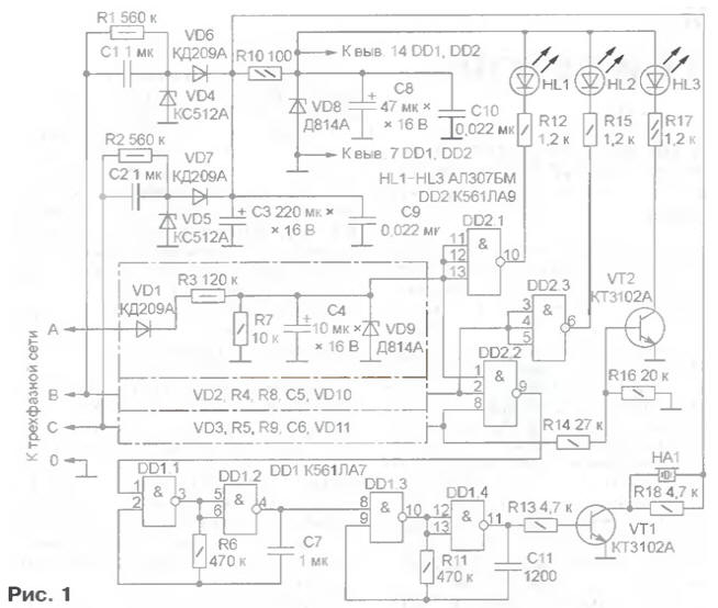
Encyclopedia of radio electronics and electrical engineering / Protection of equipment from emergency operation of the network, uninterruptible power supplies It is well known how dangerous it is for a three-phase electric motor to lose voltage in one of the phases. Only an experienced power specialist can notice this in a timely manner by changing the sound, since the engine often continues to work, but quickly overheats and burns out. In production, special protective devices are used that automatically turn off the engine when the phase voltage fails. However, for domestic use, such devices are unreasonably expensive. The proposed indicator will help prevent an accident, signaling a malfunction not only with a light signal, but also with an audible signal. The simplest indicators of the health of a three-phase network can be neon lamps connected through quenching resistors between each phase wire and neutral. Since the attention of a person is absorbed, as a rule, by the work performed, he may not notice the extinguished lamp in time. An audible signal is required to draw attention to an emergency situation. In addition, neon lamps sometimes flash randomly, so it is better to use LEDs for signaling. The scheme of the developed indicator is shown in fig. one.
The presence of voltage in each of the phases is controlled using three identical detectors. For example, the phase detector A consists of a diode VD1, a resistive divider R3R7, a smoothing capacitor C4 and a zener diode VD9 that limits the rectified voltage. With a good phase, the voltage level at the output of the detector corresponds to the log. 1, if faulty - log. 0. With a fully operational network log. 1 are present at all inputs of the element DD2.2 and log. 0 at its output blocks the operation of the tone generator on the DD1 chip. Elements DD2.1 and DD2.3 control the LEDs HL1 and HL2, the glow of which indicates the presence of voltage, respectively, in phases A and B. The phase C indicator - the HL3 LED - is controlled by a key on the transistor VT2. This is done so as not to add another microcircuit to the device. In the event of a failure of one of the phases, the corresponding LED will go out, log. 0 at the output of the element DD2.2 will change to log. 1 and the generator on the elements DD1.1, DD1.2 will start to generate pulses with a frequency of 2 ... 3 Hz, which will periodically turn on the audio frequency generator on the elements DD1.3, DD1.4. As a result, an intermittent sound signal will be heard from the piezoceramic emitter HA1. The indicator is powered by two identical rectifiers (C1. R1. VD4 and C2. R2, VD5), the inputs of which are connected to different phases of the network, in this case, B and C. Thanks to the diodes VD6 and VD7, the device actually feeds one of the rectifiers, the output voltage of which A bit more. And if one of the phases fails, the power continues from the other, the indicator remains operational. The supply voltage of microcircuits is additionally stabilized with the help of a VD8 zener diode. The indicator is assembled on a printed circuit board shown in fig. 2.
Resistors R1-R5 -MLT-0,5. Less powerful ones are not recommended for electrical safety reasons. Resistors R10 and R17 - MLT-0,125, the rest - size 1206 for surface mounting (PM). Oxide capacitors - K50-35 or the like for a voltage of at least 16 V. Capacitors C1, C2 - K73-17 for a voltage of at least 250 V, C7 - K10-17, all others - ceramic size 1206 for PM. All elements for PM (resistors and capacitors) are mounted on the side of the printed conductors, soldering directly to the pads. Instead of K561 series microcircuits, you can install (without changes in the circuit) their functional analogues from the K176 series or imported CMOS microcircuits. Transistors KT3102A can be replaced by others of the same series or series KT315, KT3117. As zener diodes VD8-VD11, any with a stabilization voltage of 7 ... 9 V (for example, KS175A, D818 with any index) are suitable, but for VD8 it should not be less than for VD9 VD11. Zener diodes VD4, VD5 are replaced by others for a voltage of 10 ... 15 V, for example, KS515A. Diodes KD209A can be replaced with KD105B or KD102B. As LEDs HL1-HL3 any suitable, preferably high brightness. HA1 - - piezoceramic sound emitter ZP-1 or similar. A correctly assembled indicator does not need adjustment and starts working immediately after switching on. If necessary, you can change the frequency of the audio signal by choosing the value of the resistor R11 or capacitor C11. Author: I.Korotkov, Bucha village, Kyiv region, Ukraine
Machine for thinning flowers in gardens
02.05.2024 Advanced Infrared Microscope
02.05.2024 Air trap for insects
01.05.2024
▪ Ultra-low power DACs from National Semiconductor ▪ Fantasists turned out to be altruists ▪ Comet Neowise is closest to Earth
▪ section of the site for the radio amateur-designer. Article selection ▪ Article Urology. Lecture notes ▪ article Which city's mayor beat his rivals in SimCity before winning the election? Detailed answer ▪ article Dill fragrant. Legends, cultivation, methods of application ▪ article Automatic car battery charger. Encyclopedia of radio electronics and electrical engineering
Home page | Library | Articles | Website map | Site Reviews
www.diagram.com.ua |


 Leave your comment on this article: