|
|


 Arabic
 Bengali
 Chinese
 English
 French
 German
 Hebrew
 Hindi
Hindi Italian
 Japanese
 Korean
 Malay
Malay Polish
 Portuguese
 Spanish
 Turkish
 Ukrainian
 Vietnamese
|
ENCYCLOPEDIA OF RADIO ELECTRONICS AND ELECTRICAL ENGINEERING Charger with discrete charging current setting
Encyclopedia of radio electronics and electrical engineering / Chargers, batteries, galvanic cells When charging different batteries, a certain charging current is required for each of them. The proposed device allows you to set 127 current values with just seven switches. This charger is designed to charge any small batteries with a voltage of 1,5 to 12 V and a charging current of 1 to 127 mA. It can be connected, for example, batteries D-0,025, D-0,06, D-0,25, D-0,55, TsNK-0,45, TsNK-0,9, as well as batteries made up of them. The charging current does not depend on the number of rechargeable batteries and can be discretely set in the above range in 1 mA steps without using a current meter. The instability of the charging current does not exceed 0,5%. When the battery reaches the voltage corresponding to full charge, the process automatically stops. The charging termination threshold voltage can be set from 1 to 12 V, depending on the type of battery or battery. The charging process is controlled by an LED. High characteristics of charging current instability are provided by a current source in which the KR142EN19 microcircuit is used [1]. This microcircuit also works well in precision current sources [2] in the range from several tens of microamperes to several amperes. The diagram of the charger with the indicated microcircuit is shown in fig. one.
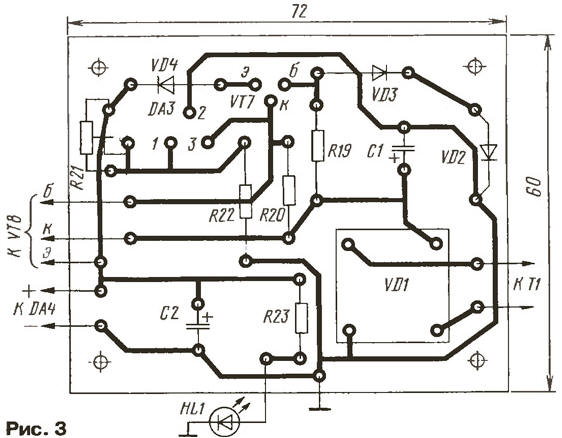
The current source is formed by the DA1 chip, transistors VT3, VT4 (they form a composite transistor) and current-setting resistors R4-R10, connected by switches SA2-SA8. The resistances of the resistors are selected so that when one of them is connected, the charging current indicated in the diagram is set. By connecting several resistors at the same time, the total current is set. For example, when the contacts of switches SA2, SA4 are closed, the total current will be 5 mA, and when the contacts of all switches are closed, the total current will reach 127 mA. If necessary, the discreteness of the current setting can be changed, making it, for example, equal to 2, 3, 5 mA. The resistance of the corresponding current-setting resistor in this case is determined by the formula R = Uon/lzar(OM), where Uon is the reference voltage of the DA1 chip (about 2,5 V); Izar - charging current, A. When choosing a different discreteness, it should be taken into account that each subsequent value of the charging current must be twice the previous one, for example, 3, 6, 12, 24, etc. Power is supplied to the DA1 chip through a key on the transistor VT2, and the resistor R3 sets its mode of operation. The rechargeable battery G1 is connected to the output of the current source through sockets (or clamps) X2 and X5. The VD3 diode prevents the battery from discharging if the device is accidentally turned off. Since the battery is charged from a stabilized source, the voltage on the collectors of transistors VT4, VT5 will be equal to the voltage difference between the power source and the battery. This voltage through the emitter follower, made on the transistor VT6, is fed to the input (pin 1006) of the comparator, assembled on the timer KR1VI3 [5]. The other input of the comparator (pin 16) is supplied with a reference voltage from the engine of the variable resistor RXNUMX. At the beginning of battery charging, the voltage at the collectors of transistors VT3, VT4 and, therefore, at pin 6 of the comparator is greater than the reference voltage supplied to its pin 5. At the same time, a low level is set at the output of the comparator (pin 3), which keeps the transistor VT1 closed. As a result, the transistor VT2 is open, which turns on the current source, and the battery starts charging. The HL2 LED lights up, which controls the operation of the current source and the charging process. As the battery charges, the voltage at the collectors of transistors VT3, VT4 and, accordingly, at pin 6 of the comparator decreases. As soon as it decreases to the voltage set at pin 5, the comparator will work. At pin 3 of the comparator, a high level will be set, which will open the transistor VT1. Transistor VT2 will close, the current source will turn off. The HL2 LED will turn off, indicating the end of the charging process. When the battery voltage drops by the value of the hysteresis voltage set by the tuning resistor R14, the charging process will resume. The power supply of the device consists of a step-down transformer T1 and two voltage stabilizers - on the elements VT7, VT8, DA3 and the DA4 chip. The first stabilizer serves as a power source for the DA2 chip and a source for charging the battery. The trimmer resistor R21 sets the output voltage of the stabilizer. To charge batteries in the range from 1 to 12 V and for normal operation of the current source, it must be 16 V. The transistor VT7 is protected against a short circuit at the output. During normal operation of the stabilizer, this transistor is closed, since the voltage at its emitter is greater than the voltage at the base. In the event of a short circuit, the voltage at the emitter becomes less than the voltage at the base, the transistor opens, the voltage at its collector decreases sharply, which leads to the closing of the VT8 transistor and the prohibition of the operation of the DA3 chip. Diode VD4 serves to increase the breakdown voltage of the emitter-base of transistor VT7, since such a voltage for most transistors does not exceed 8 V. Diode VD3, connected in the forward direction, compensates for the voltage drop across diode VD4, and together with diode VD2 creates an initial bias on the base of the transistor VT7. The second stabilizer is used to power the DA1 chip and its controls. The HL1 LED indicates that the device is connected to the network. Instead of those indicated on the diagram in the device, it is permissible to use any of the KT1, KT2, KT6 series of transistors in place of the transistors VT312, VT315, VT342, in place of VT5, VT7 - any of the same series, but with a permissible collector-emitter voltage of at least 25 V, on in place of VT3 - series KT342, KT3102 with a base current transfer coefficient of at least 100, in place of VT4, VT8 - any of the specified series LEDs - any of the series AL307. Transformer T1 - ready-made or self-made, it must provide a voltage of 18 ... 20 V on the secondary winding at a load current of 200 ... 400 mA. Diode bridge VD1 - KTS405 series with any letter index. Switch SA1 - MTZ, TP1-1, the rest - types MT1, TP1-1 or similar. Fixed resistors - MLT, variables R14, R16 - SP1-1, SP4-1 group A, tuning R21 - SPZ-1. Most parts of the device are mounted on two printed circuit boards made of one-sided foil-coated fiberglass with a thickness of 1,5 mm. On one board (Fig. 2) the main part of the device is assembled, on the other (Fig. 3) - a voltage regulator.
The VT4 transistor is mounted on an aluminum plate 4 ... 5 mm thick, the same size as the printed circuit board. The board itself is attached to the plate from above on racks 3 ... 5 mm high. Since the collector of the transistor is connected to the plate, it is necessary to remove the foil at the holes for fixing the board, and also insulate the plate if the device is installed in a metal case.
The VT8 transistor is mounted on a small radiator, which, like the transformer, is attached to the bottom cover of the device case. The case itself can be of any design, its dimensions determine the dimensions of the elements used. Setting up the charger begins with checking the voltage regulator on the DA3 chip without connecting it to the main board. In the absence of installation errors and serviceable parts, a voltage of about 1 V should be at pin 2,5 of the microcircuit. Then, with a trimming resistor R21, a voltage of 2 V is set at the output of the stabilizer (on capacitor C16). To check the stabilizer under load, a resistor MLT- is connected in parallel with capacitor C2 2 with a resistance of 120 ohms. The output voltage of the stabilizer should not differ by more than 50 mV. If it exceeds this value, select the resistor R20. To check the protection, the terminals of the capacitor C2 are closed with tweezers or a wire jumper. The HL1 LED should go out, and after removing the jumper, it will light up. After making sure that the stabilizer is working properly, check the operation of the entire device. By connecting a voltmeter to pin 1 of the DA4 microcircuit, they check the output voltage of the second stabilizer - it should be equal to 9 V. Then they close the X2, X2 sockets with a wire jumper and put the SA4 switch in the position of closed contacts. After applying power, measure the voltage at the emitter of the transistor VT2,5 - it should be about 2 V, while the HL3 LED should be lit. By selecting resistor R1, the current through the DA0,5 chip is set to 0,6 ... 4 mA. Remove the jumper from the sockets and connect a milliammeter to the sockets instead. By selecting the resistor R1, a current of 2 mA is achieved. Further, instead of the contacts of the SA3 switch, the contacts of the SA5 switch are closed and the current of 2 mA is set by selecting the resistor R6. Similarly, by selecting the remaining resistors (R10-RXNUMX), with the contacts of the corresponding switches closed, the currents indicated in the diagram are set. Of course, the process of setting charging currents can be simplified if, instead of fixed resistors R4-R10, trimmers are included. The scale of the resistor R16 is calibrated by connecting freshly charged batteries of the appropriate voltage to the sockets X2, X3. By moving the resistor slider, they achieve the moment when the HL2 LED goes out and make a mark on the resistor scale. With the help of resistor R14, the hysteresis voltage is set, at which the LED will clearly go out at the moment the battery is fully charged. Literature
Author: Yu.Lebedinsky, Alexandrov, Vladimir Region
Machine for thinning flowers in gardens
02.05.2024 Advanced Infrared Microscope
02.05.2024 Air trap for insects
01.05.2024
▪ Privateers gathered on the moon ▪ Electric liner for short flights ▪ LOG114 - new logarithmic amplifier ▪ Portable Vaccine Patch Printer
▪ section of the site Interesting facts. Selection of articles ▪ article by Marcel Proust. Famous aphorisms ▪ article What is a collage? Detailed answer ▪ article Working with an electrified tool. Standard instruction on labor protection ▪ article Physics of air ionization. Encyclopedia of radio electronics and electrical engineering
Home page | Library | Articles | Website map | Site Reviews
www.diagram.com.ua |


 Leave your comment on this article: