|
|


 Arabic
 Bengali
 Chinese
 English
 French
 German
 Hebrew
 Hindi
Hindi Italian
 Japanese
 Korean
 Malay
Malay Polish
 Portuguese
 Spanish
 Turkish
 Ukrainian
 Vietnamese
|
ENCYCLOPEDIA OF RADIO ELECTRONICS AND ELECTRICAL ENGINEERING Mains galvanic cell 373, 220/1,5 volts
Encyclopedia of radio electronics and electrical engineering / Chargers, batteries, galvanic cells The topic of developing network power supplies that replace galvanic cells in their dimensions is still of interest to our readers. Similar devices have already been described in Radio: "network" Krona ", etc. The author of the published article offers a variant of a 1,5 V power supply unit in the dimensions of element 373, which he uses to power the Slava electronic-mechanical watch. The following requirements are imposed on the source intended to power the Slava watch: 1. Small dimensions. It must fit in a battery compartment designed for cell 373. The size of the mains plug is no larger than a standard mains plug, since it can be connected to a double socket or to a multi-socket extension cord. 2. Electrical safety. The block must provide galvanic isolation of the output circuit from the 220 V network, since the clock contains metal parts - the knobs for shifting the hour hands and the alarm clock hands. It is unacceptable for them to fall on the phase of the mains voltage. 3. Load capacity. The unit must keep the clock running while the alarm is ringing. Many variants of such a power supply have been described [1-3]. The disadvantage of these devices is that the satisfaction of any one of the above requirements is to the detriment of others. For example, an increase in load capacity is achieved by increasing the dimensions, or vice versa. The proposed device is different. that it meets all of these requirements. The basis of the power supply is a self-excited high-frequency converter with a switching frequency of 80 kHz, due to which the dimensions of the isolation transformer are significantly reduced. The power supply circuit is shown in fig. one.
The mains voltage of 220 V through the quenching capacitor C1 is supplied to the rectifier diode bridge VD1. The ripple of the rectified voltage is filtered by capacitor C2. The VD2 zener diode provides input voltage stabilization at +24 V. This voltage is used to feed the high-frequency converter. It is made on transistors VT1, VT2, transformer T1, resistors R2, R3 and capacitor C3. The transformer has two input windings: collector (I), base (II) and one output winding (III). The transistors are connected in a common emitter circuit. The voltage divider R2R3 is used to start the converter when the power is turned on. In this case, a small negative voltage appears on the resistor R2, shunted by the capacitor C3, which is applied to the bases of the transistors, causing one of them to open. Capacitor C3 speeds up the switching process. For example, transistor VT1 starts to open first, and its collector current increases. In the base half-winding of this transistor, a change in the collector current induces a voltage, due to which the transistor is fully turned on. In the base half-winding of the transistor VT2, a voltage of positive polarity is induced, and this transistor remains in the closed state. This continues until the induction in the magnetic circuit of the transformer reaches saturation. This means that the change in induction (magnetic flux) stops and, therefore, the voltage in the base winding is zero, the transistor VT1 closes, and the transistor VT2 opens. This process is repeated. An alternating voltage of a rectangular shape is formed on the secondary winding of the transformer. The switching frequency depends on the supply voltage, parameters of the transformer and transistors [4]. Rectangular alternating voltage from the output winding III rectifies the diode bridge VD3. The rectified voltage smoothes the filter capacitor C4 and stabilizes the integrated regulator DA1. The need for an output stabilizer is due to the fact that the load current of the power supply changes several hundred times. The output voltage in this case should be within 1.3... 1.5 V [5]. The output stabilizer uses a KR142EN12A chip with a minimum output voltage of 1.2 V. Main characteristics of the source
The device is assembled on a double-sided printed circuit board, the drawing of which is shown in Fig. 2.
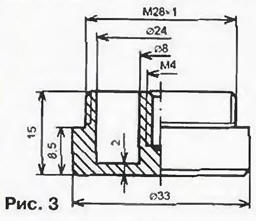
The leads of the elements are soldered directly to the printed conductors. The exception is the soldering point of the Zener diode VD2. the conclusions of which are inserted into two holes and soldered on both sides. This is necessary for the electrical connection of the sides of the printed circuit board, on one of which the capacitor C1, the resistor R1 and the diode bridge VD1 are located. The rest of the elements are located on the reverse side of the printed circuit board. The maximum power dissipated by the DA1 chip does not exceed 0.25 W and is released for about 4,5 minutes (the time the alarm clock works without stopping). Therefore, an additional heat sink for the stabilizer is not needed, moreover, the "native" heat sink of the microcircuit is cut down to reduce the size. The device uses small-sized transistors 2T664A9 [6]. intended for surface mounting, with a maximum allowable collector-emitter voltage of 100 V. which fully satisfies the conditions for their operation (the permissible collector-emitter voltage of transistors must be at least 2.2Upit 53 V). On the left side of the board, a groove is made for installing an M4 screw, to which the "minus" contact is screwed. The screw is selected with a flat cylindrical head. A petal is put on it. Then the screw is installed on the board from the side of the capacitor C1. The head of the screw, together with the attached petal, is installed in the groove. The end of the petal is bent from the opposite side of the board and soldered to the "negative" printed conductor. The case of the capacitor C1 from the side of the board should be securely insulated with varnished cloth or insulating tape, especially carefully from the side of the screw head. The DA1 chip is also isolated from the elements located on the side of the primary winding of the transformer (galvanically connected to the network) and structurally located near the chip. The transformer is glued to the board with BF4 glue. The body of the power supply is made of an industrial nozzle designed to turn element 343 into 373 in terms of dimensions. The negative contact of the block is made of metal according to the drawing in fig. 3. With the help of an external thread, a mechanical connection ("snapping") of the negative contact and the board screwed to it with the block body is carried out.
The device uses capacitors: C1 - K73-17 for a voltage of at least 400 V; C2 - K53-1 A; C3. C5 - K10-17-16. C4 - K52-1. Instead of 2T664A9 transistors, you can use KT208L or KT208M transistors. instead of the diode bridge KD906A - diodes KD510A. The transformer is wound on a ferrite ring K 10x6x2 brand 2000NM1. The collector winding contains 2x90 turns of PEV-2 wire with a diameter of 0.1 mm, the base winding contains 2x15 turns of the same wire. The secondary winding consists of 20 turns of wire PEV-2 0,27. It is carefully isolated from the primary windings with several layers of varnished cloth. Establishing a power supply comes down to the correct phasing of the base windings (II) and the selection of the resistor R5 of the stabilizer divider. To protect the VD1 diode bridge from current surges when turned on, it is advisable to include a resistor with a resistance of 100 ohms and a power of 0,5 W in the gap of the lower network wire according to the network wire diagram. Literature
Author: O. Sidorovich, Lviv, Ukraine
Machine for thinning flowers in gardens
02.05.2024 Advanced Infrared Microscope
02.05.2024 Air trap for insects
01.05.2024
▪ Nanowire instead of a hard drive ▪ Disney Robot Companion for Single People ▪ Dell Latitude 9000, 7000 and 5000 laptops ▪ Ball lightning - maybe it's just an illusion ▪ Airbus helicopter on green fuel
▪ section of the site RF power amplifiers. Article selection ▪ article Coming Ham. Popular expression ▪ article Which insect males steal wedding gifts from other males, mimicking a female? Detailed answer ▪ article Responsible editor (copywriter). Job description ▪ article Imitator of sounds of a drop. Encyclopedia of radio electronics and electrical engineering ▪ article Economic triac control device. Encyclopedia of radio electronics and electrical engineering
Home page | Library | Articles | Website map | Site Reviews
www.diagram.com.ua |


 Leave your comment on this article: