|
|


 Arabic
 Bengali
 Chinese
 English
 French
 German
 Hebrew
 Hindi
Hindi Italian
 Japanese
 Korean
 Malay
Malay Polish
 Portuguese
 Spanish
 Turkish
 Ukrainian
 Vietnamese
|
ENCYCLOPEDIA OF RADIO ELECTRONICS AND ELECTRICAL ENGINEERING Voltage stabilizers with a chip KR142EN19A
Encyclopedia of radio electronics and electrical engineering / Surge Protectors Unlike a conventional zener diode, KR142EN19A has leads not only for the anode and cathode, but also for the control input (Fig. 1, a). Here, under the anode we will understand the electrode to which the plus of the stabilized voltage is supplied. A microcircuit is produced in a package resembling a transistor (Fig. 1, b).
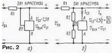
By applying voltage from the anode (Fig. 2, a) or a resonant divider (Fig. 2,6) connected between the anode and cathode to the control input, it is possible to change the stabilization voltage from 2,5 to 30 V.
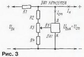
The stabilization current can be within 1 ... 100 mA, and the differential resistance does not exceed 0,5 Ohm. The highest dissipation power reaches 0,4 W, and the control input current is 5 μA. It is advisable to choose a current through a resistive divider of at least 0,5 mA. To build a low-power voltage regulator (parallel type), a ballast resistor (R1 in Fig. 2) is connected in series with the microcircuit, and the load is connected to the anode and cathode terminals, as is the case with a conventional zener diode. Such a stabilizer is calculated by a method similar to that of a zener diode. If you need to smoothly change the output voltage of the stabilizer, a variable or trimming resistor is introduced into it (Fig. 3). Then the minimum voltage can be easily calculated using the formula: formula: Umin = 2.5 [1 + R2/(R3 + R4)] V. and the maximum Umax = = 2.5 [1 + (R2 + R3)/R4] V. Ballast resistance the resistor is determined as follows: R1 \u1d (Uin min - Uout) / (Ictmin + Idep + Istmax). where Istmin can be taken equal to XNUMX mA.
If the load must consume more current than the microcircuit can provide, a bipolar transistor (Fig. 4) of the appropriate power is introduced into the stabilizer. It should be noted that the resistive divider in this case is connected between the output of the stabilizer and the common wire. The result is a compensation voltage regulator with a regulating transistor. Despite its simplicity, such a stabilizer often outperforms specialized integrated voltage stabilizers (chips of the K142, KR142 series).
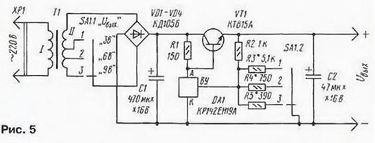
On fig. 5 shows a diagram of a stabilized power supply with a KR142EN19A chip, which is designed to work with a player, a low-power radio receiver and other equipment. It is convenient to build it into a network adapter with an unstabilized and switchable output voltage.
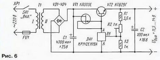
The transformer, diode bridge and filter capacitor C1 are used from the adapter. Instead of the existing switch in one direction, you will have to install a similar one in size in two directions. Most of the parts are placed by the method of surface mounting, the transistor (KT815A-KT815G, KT817A-KT817G) is supplied with a heat sink. The resistance of each of the resistors R3 - R5 is calculated by the formula: R = R2 / (Uout / 2,5-1). When testing this block, very good results were obtained: the stabilization coefficient was several hundred, and the amplitude of the output voltage ripple at a load current of 200 mA was no more than 2 ... 3 mV. When setting up the unit, the output voltages are more accurately set by selecting resistors R3 - R5. A more powerful unit, which was used to power a stationary CB radio station with an output power of 10 W, was made according to the circuit shown in Fig. 6. Here, to increase the stabilization factor, instead of a resistor, a current stabilizer on a field-effect transistor is used, and to provide an output current of 3 A or more, a powerful composite bipolar transistor with a base current transfer coefficient of 1000 or more is used. The output voltage can be adjusted within small limits (11,5 ... 14 V) with a tuned resistor R2.
Transformer T1 must provide an alternating voltage of about 15 V on winding II at maximum load current. The diodes of the rectifier bridge and the transistor VT2 are selected for the same current (it is installed on the heat sink). When testing the block, the stabilization coefficient at a load current of 2 A turned out to be more than 1000, and the output resistance was about 0,005 Ohm. Author: I. Nechaev, Kursk
Artificial leather for touch emulation
15.04.2024 Petgugu Global cat litter
15.04.2024 The attractiveness of caring men
14.04.2024
▪ The world's fastest internet network ▪ The robot ran 5 km without stopping
▪ section of the site Normative documentation on labor protection. Article selection ▪ article Despicable metal. Popular expression ▪ article What is seasickness? Detailed answer ▪ article Red or green? Radio - for beginners ▪ article Automated lighting control. Encyclopedia of radio electronics and electrical engineering ▪ article Magic coin. Focus Secret
Home page | Library | Articles | Website map | Site Reviews
www.diagram.com.ua |


 Leave your comment on this article: