|
|
ENCYCLOPEDIA OF RADIO ELECTRONICS AND ELECTRICAL ENGINEERING Connecting small-sized remote 120-volt power supplies to a 220 V network. Encyclopedia of radio electronics and electrical engineering
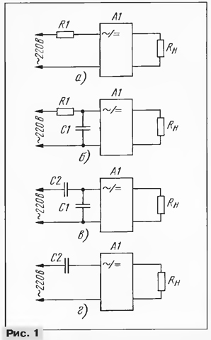
Encyclopedia of radio electronics and electrical engineering / Power Supplies Small-sized remote power supplies, made in the form of a mains plug (they are also called adapters), are equipped with various household radio equipment (telephones, calculators, radios, etc.). Unfortunately, it is not uncommon for such a unit to be designed for a mains voltage of 120 V. How they can be connected to a 220 V network is discussed in the proposed article. A small-sized remote power supply (A1 in Fig. 1), designed for an input voltage of 120 V, can be connected to a 220 V network in at least four ways. Let's consider them on the example of the Panasonic KX-A09 block, which is equipped with cordless phones KX-TS910-B. On its body are indicated: input voltage - 120 V at a frequency of 60 Hz; power consumption from the network - 6 W; output parameters: voltage - 12 V; direct current - 200 mA.
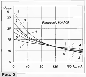
At a frequency of 50 Hz, the input voltage must be reduced. Therefore, it is impossible to obtain the passport value of the output voltage from the power supply; most likely, it cannot be used to power the device with which it was included. If the network frequency is 50 ... 60 Hz, it, of course, can be used for its intended purpose. On fig. Figure 2 shows the dependence of the output voltage of the considered small-sized remote power supply on the load current at an input voltage of 105 V (curve 1). To obtain comparable results, all additional elements (R1, C1, C2 in Fig. 1) were subsequently selected so as to provide an output voltage of 11,8 V at a current of 120 mA (load resistance - 98 Ohm). The simplest, but least efficient, connection option is shown in Fig. 1a. The resistance of the resistor R1 can be calculated, as recommended, in [1], or you can pick it up. First, its resistance should be evaluated using a semi-empirical formula that ensures that the unit is not overloaded: R1 = 22/P where R1 is the resistance of the resistor, in kiloohms, P is the power consumed by the unit, in watts. In the case under consideration, R1 = 22/6 = 3,6 kOhm. Next, the load is connected and, gradually reducing the resistance of the resistor, the required output voltage is achieved. It is better, of course, to use a wire-wound variable resistor with the appropriate power. To obtain the required output voltage, a 2,44 kΩ resistor was required. The dependence of the output voltage on the load current for the selected resistor R1 is shown in fig. 2 (curve 2). It can be seen that the voltage drops more sharply with increasing current.
To reduce losses, according to the recommendation in [1], a capacitor was connected in parallel with the primary winding of the power supply transformer, the capacitance of which was selected to ensure resonance (see Fig. 1, b). On fig. 3 shows the dependence of the output voltage on the capacitance of the capacitor. Although the resonance is noticeable, its role is negligible - the voltage increases by only 1,5%. To maintain the output voltage at a given level with the capacitance of the capacitor C1 = 0,44 μF, the resistance of the resistor R1 was increased to 2,57 kOhm. The load characteristic of the unit (Fig. 2, curve 3) in this variant of inclusion differed little from curve 2.
It is quite natural to replace the resistor R1 with a capacitor (see [2], where the operation of a capacitor divider is considered in relation to a non-linear active load). While maintaining C1 = 0,44 μF, the capacitance of the capacitor C2 was required to be 0,54 μF (see Fig. 1, c). The load characteristic for this case is less steep (curve 4 in Fig. 2). To an even greater extent, it is possible to reduce the dependence of the output voltage on current by increasing the capacitances of capacitors C1 and C2. For example, with an arbitrarily chosen capacitance C1 = 1 μF, the capacitance of the capacitor C2 selected to provide a given voltage was 0,67 μF (curve 5 in Fig. 2). On the other hand, if the stability of the output voltage with a change in the load current is not fundamental or the load current practically does not change, capacitor C1 can be excluded (see Fig. 1, d). The selection of capacitance can be started with a value calculated by the semi-empirical formula: C2 = P/12, where C2 is the capacitance of the capacitor, in microfarads; P is the power of the block, in watts. The formula takes into account the margin that excludes overloading the power supply. For the case under consideration, the initial capacitance of the capacitor C2 \u6d 12/0,5 \u2d 0,76 μF. With a selected capacitance C0 = 200 μF and a change in the load current from 27 to 8,9 mA, the output voltage changes from 6 to 2 V (curve XNUMX, Fig. XNUMX). It is interesting to note that the capacitance of the capacitor C2 turned out to be greater than for the variant in Fig. 1, in. This is due to the partial mutual compensation of reactive currents through the capacitor C1 and the inductance of the primary winding of the transformer. Thus, if the stability of the output voltage is required when the load current changes, it is most advisable to use a capacitor divider. If stability does not play a role, use the option with one capacitor C2 (see Fig. 1, d). It is not advisable to use the options for connecting the power supply (see Fig. 1, a and b) due to large power losses and strong heating of the ballast resistor. Shown in fig. 2 graphs illustrate the dependences of the average value of the output voltage. In reality, a ripple voltage is applied to it, its shape is close to sawtooth, and the amplitude practically does not change depending on the connection method (see Fig. 8 in [3]). For the options in Fig. 1, c and d parallel to the capacitor C2 for discharge after disconnecting the power supply from the network, install a resistor with a resistance of several hundred kilo-ohms. In addition, in the variant of Fig. 1, in it is desirable to connect a current-limiting (at the time of connection to the network) resistor with a resistance of 2 ... 22 Ohm in series with capacitor C47. The rated voltage of the capacitors must be at least 250 V, K73-16 and K73-17 are very convenient. In all experiments, it should be remembered that the nominal voltage of the oxide filter capacitors installed in small-sized remote power supplies is usually 16 V, and therefore applying a higher voltage to them for any long time is undesirable. Literature
Author: S. Biryukov, Moscow
Machine for thinning flowers in gardens
02.05.2024 Advanced Infrared Microscope
02.05.2024 Air trap for insects
01.05.2024
▪ PLM-40E - 40W Step Dimming LED Driver ▪ I waste household appliances - banned ▪ New series of wet tantalum capacitors with maximum capacitance ▪ New BiCMOS Manufacturing Technology for VIP50 Analog ICs
▪ section of the site Metal detectors. Article selection ▪ article Gardens of Armida. Popular expression ▪ article Why can't animals talk? Detailed answer ▪ article A cache that is always with you. Spy things ▪ article Masses for molding various objects. Simple recipes and tips
Home page | Library | Articles | Website map | Site Reviews www.diagram.com.ua |


 Arabic
 Bengali
 Chinese
 English
 French
 German
 Hebrew
 Hindi
Hindi Italian
 Japanese
 Korean
 Malay
Malay Polish
 Portuguese
 Spanish
 Turkish
 Ukrainian
 Vietnamese


 Leave your comment on this article: