
|
|
ENCYCLOPEDIA OF RADIO ELECTRONICS AND ELECTRICAL ENGINEERING economical stabilizers. Encyclopedia of radio electronics and electrical engineering
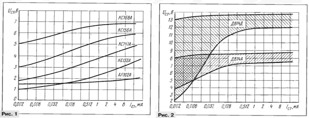
Encyclopedia of radio electronics and electrical engineering / Surge Protectors Without going into a detailed analysis of the advantages and disadvantages of various principles of voltage conversion and stabilization, the author of the article shares his experience in developing simple economical voltage stabilizers with a bipolar transistor as a regulating element. Much attention is paid to the choice of the exemplary voltage source. The article provides tables with the results of testing various stabilizers, making it easier to choose the right option. To achieve high efficiency of radio-electronic devices powered by galvanic cells or batteries and requiring a stabilized voltage, in addition to the correct choice of supply voltage and type of cells, it is important to choose an appropriate economical stabilizer that ensures the longest possible operation of the device without replacing power sources. An economical (with high efficiency) is a stabilizer that simultaneously satisfies two conditions: first, it must have a low current consumption compared to the load current; secondly, to have the minimum allowable voltage drop across the regulating element. In the literature, there are often descriptions of economical stabilizers, in which the authors focus on reducing the current consumed by the stabilizer itself and do not attach much importance to the fact that for its normal operation, the input voltage must exceed the output voltage by at least 1,5 ... 2 V. When powered from batteries, this circumstance plays a paramount role. Simple calculations show that the decrease in the efficiency of stabilizers occurs precisely because of the dissipation of energy in the form of heat on the regulating transistor, and these losses are directly proportional to the voltage drop. In general, the stabilizer is an adjustable voltage divider, where a transistor is used as a regulating element, the conductivity of which changes the control element. In economical stabilizers, the control element must provide sufficient base current of the regulating transistor with minimal own consumption. This current is generated by comparing the output voltage with the reference voltage. The correct choice of a reference voltage source (ION) is important, the parameters of which determine the characteristics of the stabilizer: stabilization coefficient (Ket), temperature coefficient of voltage (TKN), efficiency, etc. The regulating transistor must maintain a stable output voltage when the supply voltage decreases to a minimum value slightly exceeding the rated output voltage of the stabilizer. The minimum difference between the input and output voltages, at which the stabilizer can still maintain the rated output voltage, also depends on the connection diagram of the regulating transistor [1]. MICROPOWER REFERENCE VOLTAGE SOURCES The simplest ION circuit is obtained using zener diodes, the choice of which is quite large, but in practice difficulties often arise due to the spread of the stabilization voltage of zener diodes of the same type and low efficiency when powering micropower devices. It is generally accepted that zener diodes are unsuitable for operation at a current of less than 0,5 ... 1 mA. This is true when you need to get a guaranteed result without spending time checking and selecting suitable zener diodes. However, most of them can operate at a lower current, providing acceptable parameters for a load current not exceeding several tens of microamperes. To verify this, it is enough to draw the dependences of the parameters of the zener diodes not on a linear scale, as is done in most reference books, but on a logarithmic scale. On fig. 1 - 3 shows the dependence of the stabilization voltage (UCT) and differential resistance (Rd) on the stabilization current (lCT) on the indicated scale.
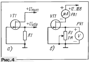
Due to the fact that the parameters of the zener diodes are characterized by a large spread, the dependences of the stabilization voltage on the current for the zener diodes KS133A, KS147A, KS156A, KS168A are averaged characteristics (Fig. 1). For zener diodes of the D814 series, which have a particularly strong spread at a current of less than 200 ... 300 μA, the graphs are shaded areas (Fig. 2), built on the basis of a generalization of the characteristics of several (up to five) zener diodes of each type. The small number of zener diodes tested does not allow drawing conclusions that claim to be more accurate, but some general trends are still visible. Tests have shown that for Zener diodes D808 - D811, D813, D814 and D818 series, with a decrease in current, the stabilization voltage initially decreases slightly, but at a current of less than 200 ... 300 μA, in some instances it becomes unpredictably low. For low-voltage zener diodes KS133A, KS147A, KS156A, with a decrease in current, the stabilization voltage monotonously decreases without sharp dips. The graph for the KS133A and KS147A zener diodes (Fig. 3) is an almost straight line showing the inversely proportional dependence of the differential resistance on the current. A decrease in current by a factor of 1000, for example, from 32 mA to 32 μA, leads to an increase in Rd also by a factor of 1000 - from 10 Ω to 10 kΩ. Zener diodes with a stabilization voltage of 5,6 ... 7 V and a current of more than 3 mA have a lower differential resistance. With a decrease in current to a certain level, Rd of such zener diodes increases sharply, and with a further decrease in it, it does not differ much from Rd of lower-voltage zener diodes. Zener diodes D814A - D814D also have low differential resistance at high current, but at a current of less than 200 ... 300 μA, Rd of some examples of zener diodes can be much larger than that of low-voltage ones. Experiments with several instances of zener diodes (KS510A, KS512A, KS515A, KS518A) showed that most of them have good stabilization characteristics in the entire range of current changes up to 3 ... 5 μA, but they are designed for voltage stabilization of more than 10 V. Their feature is an increased noise level at a current of less than 300 μA. One should not underestimate such an ION parameter as the voltage temperature coefficient, since it can cause such unpleasant phenomena as the local oscillator frequency drift or an increased error of the measuring device when the ambient temperature changes. TKN of zener diodes with UCT = 5...6,8 V (KS156A, KS168A, etc.) with a decrease in current to 100 μA and below shifts towards negative values and can increase to -2,5 mV/°С [2 ]. Thermally compensated zener diodes of the D818, KS191 series, etc. at a current of less than 1 mA, they lose their precision properties due to an increased negative TKN. Among the zener diodes of the D814 series, there are instances that are unsuitable for operation in low current mode (less than 0,3 ... 0,4 mA) due to a sharp decrease in the stabilization voltage when the temperature drops. For most other types of zener diodes, as the current decreases, the TKN does not change so noticeably, but the general trend is the shift of the TKN towards negative values. An analysis of the characteristics of zener diodes at low current allows us to draw the following conclusions. Almost all types of zener diodes are quite applicable in the low current mode, but only after a preliminary test. In this case, you should choose those instances in which, with a decrease in the supply current, the stabilization voltage changes less. Zener diodes with UCT < 7 V (KS133A, KS139A, KS147A, KS156A, KS168A) can be used in ION with a reduced supply current up to several tens of microamperes. The stabilization coefficient of the zener diodes KS133A, KS139A and KS147A is almost independent of the current, but has a low value (6 ... 10), and the stabilization voltage monotonically decreases with decreasing current and at a value of 50 μA it can be 1,5 ... 2 times less than at 5...10 mA. This circumstance makes it possible to regulate the stabilization voltage within certain limits by changing the current, but it is desirable to stabilize the current in order to increase the KCT [3]. The stabilization coefficient of the KS156A and KS168A zener diodes decreases to 8 ... 15 with a decrease in current, which may also require the use of current stabilization. The stabilization voltage when the current decreases to 50 μA decreases by 1,2 ... 1,5 times. Zener diodes with UCT = 7,5 ... 14 V (D808, series D814 and D818, etc.) are applicable in ION at a current of up to 0,4 ... 0,5 mA with a slight deterioration in parameters; at a value of less than 0,4 mA, the characteristics may deteriorate, but more than half of the tested zener diodes of this type had acceptable parameters when the current decreased to 80 ... 100 μA. A good alternative to zener diodes, especially in low current mode, are LEDs [4] of visible radiation (UCT = 1,5 ... 2 V in direct connection) and base-emitter junctions [5-7] of low-power silicon transistors (UCT = 4. ..10 V when switched back on). They provide a higher CCT and can work even if the stabilization current is less than 20 µA, and the stabilization voltage of the LEDs in low current mode is quite predictable. In ION, not only p-n junctions of diodes and transistors can be used, but also field-effect transistors used as a current stabilizer (Fig. 4, a). The reference voltage is removed from the resistor in the source circuit [8]. At a current of 10 µA, this voltage is equal to the cut-off voltage (UOTC) of the FET. The value of the current flowing through the field-effect transistor is selected by changing the resistance of the resistor in the source circuit. The main disadvantage of field-effect transistors is the large spread in the cutoff voltage of devices of the same type, even within the same batch (package), which in most cases makes it impossible to use them without first measuring this parameter and selecting a suitable transistor.
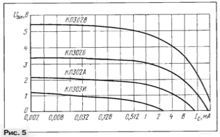
To measure UOTC, it is necessary to connect a microammeter to the drain of the transistor, and a voltmeter in parallel with the resistor (Fig. 4, b). Set the drain current to 10 µA with a variable resistor and measure the voltage drop across the resistor (or between gate and source) using some kind of high-resistance voltmeter. This voltage can be considered as the cutoff voltage. It is more convenient to select transistors if you insert them into some suitable small-sized connector, to which wires from other devices are soldered. On fig. 5 shows the dependence of the source voltage on the drain current for several field-effect transistors. It can be seen from the graphs that when the current changes from 1 to 150 ... 200 μA, the voltage at the source of most transistors changes by no more than 20 ... 25% of the cutoff voltage. This circumstance can be useful in making approximate calculations. The stabilization coefficient at a current of less than 1...2 mA is in the range of 20...40, slightly increasing with decreasing current. TKN has a maximum positive value at low current and decreases with its increase, becoming negative at a current of more than 0,1-3,0 mA [9].
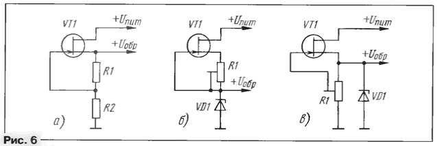
Studies have shown that the most suitable for use as microcurrent IONs are transistors with a p-n junction of the KP103, KP302 and KP303 series. For most of them, TKN in low current mode does not exceed +2,5 mV/°C or 0,25%/°C. The use of transistors with an insulated gate (only transistors of the KP305 and KP313 series were studied) is also not excluded, but their TKN spread is greater. Since the current stabilizer on a field-effect transistor is a two-terminal one, the series connection of an additional resistor (Fig. 6, a) allows you to increase the exemplary voltage. By replacing the resistor in the source circuit with a potentiometer and adjusting the feedback voltage at the gate, you can increase the voltage at the source of the transistor from UOTC over a wide range, but it is better to limit yourself to 2 ... This allows you to improve the TKN. The disadvantages of ION according to such a simple circuit are a relatively high output impedance and an increased positive TKN. To improve these parameters, and at the same time to increase Kst to 50 ... 80, a combination of a current stabilizer with zener diodes having a negative TKN (KS133A, KS139A, KS147A, KS156A, KS168A) (Fig. 6,b) allows. The minimum supply voltage should be higher than the reference voltage by the UOTC value with some margin, therefore, if the input voltage is not much higher than the stabilization voltage, it is better to choose field-effect transistors with a small UOTC. With a variable resistor in the gate circuit, by changing the stabilization current within certain limits, you can adjust the exemplary voltage of the ION.
LEDs and zener diodes KS119A, KS133A, KS139A, KS147A to "save" the supply voltage are connected in parallel with a variable resistor in the source circuit of the field-effect transistor (Fig. 6, c). The resistance of the resistor can be from several hundred kΩ to several MΩ. The cutoff voltage of the field effect transistor should be slightly less than the reference voltage of the ION, so more common field effect transistors with U0TC> 1 V can be used. The reference voltage can be adjusted within a small range by changing the stabilization current. A zener diode connected in parallel with the resistor stabilizes the voltage at the source of the transistor and worsens the feedback at the gate. Therefore, such inclusion is effective only for low-voltage zener diodes with an insignificant stabilization coefficient. It is possible to improve the parameters of an ION based on a current stabilizer using an additional bipolar transistor (Fig. 7a). Unlike zener diode analogues using only bipolar transistors [10 - 12], this device contains fewer parts, works well in low current mode and has a low TKN. It is better to use a bipolar transistor with a low-power silicon with a high current transfer coefficient of the KT3102, KT3107, KT342, etc. series, since the operating range of the current of such an analogue of a zener diode is directly proportional to the current transfer coefficient (h21E) of the VT2 transistor. The negative TKN of the base-emitter junction of the bipolar transistor partially compensates for the positive TKN of the field-effect transistor, therefore the total TKN is in the range of -0,02 ... + 0,04% / ° С in the lower position of the variable resistor slider (in the case of using field-effect transistors with p -n transition).
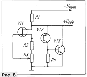
On fig. 7b shows the current-voltage characteristics of the zener diode analogue at different positions of the variable resistor slider. As you can see, the operating current interval of the device is limited. The minimum stabilization current is determined by the resistance of the resistor in the source circuit (this current must be sufficient to create a voltage drop equal to the reference), and the maximum current with the selected resistance of the resistor R2 is determined by the current transfer coefficient of the transistor VT2 (the maximum base current, and therefore the collector, is limited by the resistor , therefore, with an increase in the stabilization current, the exemplary voltage also begins to increase). With an increase in the reference voltage by a factor of 2 (with a potentiometer in the source circuit), the minimum and maximum stabilization currents also increase by about 2 times. TKN in this case can increase up to +0,08%/°C. A simplified calculation of the zener diode analogue is carried out in the following sequence: the minimum stabilization current is determined, the field-effect transistor with a certain cutoff voltage is selected, the resistance of the resistor in the source circuit is calculated, and the maximum stabilization current is determined. For the calculation, you can use the ratios: Ist min >51H; Uobr min=U0TC + UBE or U0TC=U0br min-0,6 V; Ri=2U0TC/lCT min (if Uobr is not regulated); Ri2 (Uobr max-0,6B) / lst min (if Uobr is adjustable); Iст max=lK max/2=(lБ-h21э)/2=(U0TC/Rи)h21э/2=U0TC·h21э/2Rи. where Ist min - minimum stabilization current; IH - maximum load current; Ist max - maximum stabilization current; lK max - maximum collector current of transistor VT2; IB - base current of the transistor VT2; R and - resistance of the resistor (or resistors) in the source circuit; Uobp min - minimum reference voltage; UOTC - cutoff voltage of transistor VT1; UBe - voltage drop at the base-emitter junction of the transistor VT2; h21e - static current transfer coefficient of the transistor VT2; 2 is an empirical coefficient that takes into account the deterioration of parameters near the limiting stabilization current. You can expand the operating current range of the zener diode analogue by adding another transistor (Fig. 8). This transistor, if it is necessary to stabilize a large current, can be powerful, mounted on a heat sink or directly on a metal case (if the transistors VT2 and VT3 are of the same structure).
The analogue of the zener diode (Fig. 8) surpasses most of the zener diodes in its parameters, especially when stabilizing a small current. The advantage is the ability to regulate the exemplary voltage over a wide range. When calculating a three-transistor analogue of a zener diode, instead of the parameters of the transistor VT2, the parameters of the composite transistor are substituted into the formulas. Resistor R4 serves to eliminate the influence of the collector reverse current and can have a resistance of several tens to several hundred kOhm, depending on the stabilization current change interval. The disadvantage of the circuit is the poor predictability of the TKN, which, moreover, changes during the regulation of the reference voltage. As the voltage increases, the TKN shifts towards positive values. For example, an analogue of a zener diode assembled on complementary transistors (taking into account a different structure): transistor VT1 - KP103E (UOTC \u1d 2 V), transistor VT3102 - series KT21 (h320e \u3d 3107), transistor VT21 - series KT190 (h2e \u3d 1), R40 =R3=5 MΩ, had a stabilization coefficient of at least 1,5 at a current of 2,5 μA to 0,06 mA. The exemplary voltage was regulated within 0,07...XNUMX V. In this case, the temperature coefficient of the voltage varied from -XNUMX%/°C to +XNUMX%/°C. The same analogue of a zener diode with a VT1 KP302B transistor (UOTC=3,4 V) had a stabilization coefficient of at least 100 at a current of 10 μA to 10 mA. The exemplary voltage was regulated within 3,9...7 V. TKN varied from -0,01%/°С to +0,02%/°С. CIRCUIT DESIGN OF ECONOMIC STABILIZERS The basis for the development of economical stabilizers is a simple stabilizer with short circuit protection (Fig. 9), which has been popular with radio amateurs for more than two decades [13].
The principle of its operation is based on comparing the output voltage with the voltage on the zener diode VD1. The reference level is applied to the base of the transistor VT2, and the output voltage to the emitter. The error signal is amplified by the transistor VT2 and fed to the base VT1. Elements R1, R2, VD1, VT2 form a current stabilizer, so the maximum output current of the stabilizer is limited. When the load resistance decreases, the output current of the stabilizer increases to the limiting level (Ilimit), then the output voltage decreases. When at the output it drops to the value UVD1 - UVD2 or UVD1 - 0,6 V, the opened diode VD2 shunts the zener diode VD1. In the event of a short circuit, the signal level at the base of the transistor VT2 will be equal to the voltage drop at the pn junction of the diode VD2 in direct connection. This reduces the collector current of the transistor VT2, and, therefore, the output current of the stabilizer in the event of a short circuit (lK3) will be less than the limiting current. The output voltage of the stabilizer is determined by the ratio Uvyx = UVD1 - UBE VT2 + UVD3, where UVD1 is the stabilization voltage of the zener diode; UBE VT2 - voltage drop at the base-emitter junction of the transistor VT2; Uvd3 - voltage drop across the VD3 diode in direct connection. Since UBE VT2 \u3d UVD0,6 \u1d XNUMX V, we can assume that the output voltage of the stabilizer is equal to the stabilization voltage of the zener diode VDXNUMX. Stabilization coefficient (Kst) stabilizer Kst \uXNUMXd (ΔUin / ΔUout) (Uout / Uin), where ΔUin and ΔUout are the voltage increments at the input and output of the stabilizer, respectively; almost equal to Kst zener diode VD1. The voltage temperature coefficient (TKV) of the stabilizer is approximately equal to the TKN of the VD1 zener diode, since the TKN p-n junctions of silicon transistors and diodes are the same and have a value of about -2mV / ° С, and from the expression for the output voltage it can be seen that they are mutually subtracted. The output impedance of the stabilizer Rout = ΔUout / ΔIN where ΔIN - load current increment; mainly depends on the gain of the transistor VT1 and the selected value of the output current limit (lorp). The stabilizer limiting current is set by selecting a resistor R2, the resistance of which determines the ratio R2 = (UVD1-UBE VT2) / IE VT2, where UBEVT2 = 0,6 V; IE VT2 - the emitter current of the transistor VT2, which is approximately equal to the base current of the transistor VT1 (IB VT1). The base current of the transistor VT1 is related to the output current of the stabilizer by the expression IBVT1 \u21d Ivyx / h1E VTXNUMX. so you can write R2 \u1d (UVD0,6-21 V) h1E VTXNUMX / lorp. To ensure the minimum voltage drop, the current Iorp is chosen not less than (2 ... 3) In. The main characteristics of the stabilizer, tested with different zener diodes, are given in table. 1.
For all options: transistor VT1 - KT3107 series (h21E = 230); transistor VT2 - KT3102 series (h21E = 200); diodes VD2, VD3 - KD103A; current consumption of the stabilizer (no load) is 8...10 mA at Uin = 2Uout; Rout = 2,0 Ohm at In = 20 mA; Iorp = 60...70 mA; Ikz = 20 mA; Kst was determined at Uin = 2Uout. The minimum voltage drop ΔUmin = Uout - Uout is determined as follows (Fig. 10): Uout of the stabilizer is measured at Uin = 2Uout and rated load current (in this case 20 mA), then Uin is reduced to Uout and the new value Uout is measured. The difference between these voltage - the most important parameter of an economical stabilizer designed for battery operation. With a more rigorous approach, this parameter cannot be called the minimum voltage drop; such a definition is rather conditional. The minimum voltage drop across the stabilizer depends on the allowable decrease in the output voltage, which may vary depending on the nature of the load, but the proposed method for measuring ΔUmin is more convenient and versatile, as it allows you to compare the parameters of different stabilizers without taking into account the requirements of a specific load.
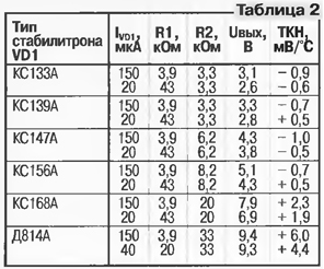
It should be noted that this parameter is highly dependent on the load current, as well as on the level of output current limitation and the quality of the zener diode. When using zener diodes with a large voltage drop in the low current region (KS133A, KS139A, KS147A, KS156A), even with a load current of less than 20 mA, it is not possible to obtain ΔUmin less than 0,6 V. From Table. 1 shows that the characteristics of the stabilizer are rather mediocre, especially when stabilizing low voltage, and almost completely depend on the parameters of the reference voltage source (ION), made in the form of a simple parametric stabilizer (R1VD1). The exemplary voltage is chosen too high, it is equal to the output voltage of the stabilizer, therefore, when Uin decreases to Uout, the current through the zener diode drops sharply, which leads to a decrease in the voltage at the zener diode and, accordingly, at the output. The current of the zener diode, selected by conventional methods, is unreasonably large compared to both the base current of the transistor VT2 and the load current, so the efficiency of the stabilizer is rather low. To improve the characteristics of the stabilizer, it is necessary first of all to improve the parameters of the ION by reducing the reference voltage and current consumption, in addition, to improve Kst, it is necessary to stabilize the supply current of the zener diode. You can reduce the exemplary voltage at the zener diode VD1 by increasing the voltage drop across the VD3 diode: instead of a silicon diode, you must use LEDs, for example, the AL102 series with a direct-on voltage drop of about 1,7 V. Here Uout of the stabilizer is more than the exemplary one by about 1,1 V. The use of low-voltage zener diodes or stabistors is undesirable, as this worsens the parameters of the stabilizer. To stabilize the current flowing through the zener diode VD1, instead of the resistor R1, you can use a field-effect transistor (see Fig. 6, b). Since at Uin = Uout the voltage drop across the current stabilizer is 1,1 V, then in order to obtain a small value of ΔUmin, the field-effect transistor must have Uots < 0.V5 V. This requirement complicates the selection of the transistor, since most suitable types of field-effect transistors have Uots > 1 V (in network power supplies, this problem is practically absent). If any low-power silicon diode is connected in series with the AL102 series LED, then with a slight deterioration in the parameters, field-effect transistors with Uots up to 1,2 V can be used. the formula for the output voltage takes the following form: Uout = UVD1 + 1,7V. To reliably start the stabilizer, with a reduced supply current of the zener diode VD1, it is necessary to connect another diode in series with the VD2 diode. This is due to the fact that at a current of less than 1 mA, the voltage drop across the VD2 diode (at the moment of switching on or after the short circuit has been eliminated) may be less than the base-emitter voltage of the VT2 transistor, which is necessary to open it and start the stabilizer (especially at low temperatures). If the short circuit current is too high, then one of these diodes can be replaced with germanium (series D9, DZ10, etc.). An improved version of the stabilizer with a current stabilizer based on a KP303B field-effect transistor (Uots = 0.B4 V) was tested with different types of zener diodes at two current values lVD1. The following results are obtained: Kst = 50...100; ΔUmin not more than 0,14 V at IН = 20 mA and not more than 0,20 V at lН = 30 mA; Rout = 2,0 Ohm; Ipotr (no load) no more than 0,7 mA; Ikz at Uin = 2Uout no more than 50 mA (diodes VD2 and VD3 - KD103A and Ilimit = 65...100mA). The output voltage at different values of current through the zener diode and the resistance of the resistors (R1 is the resistor in the source circuit of the field-effect transistor) are presented in Table. 2.
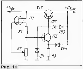
With low-voltage zener diodes KS119A, KS133A, KS139A, KS147A, as well as with LEDs, a current stabilizer should be used (see Fig. 6, c). Here you can use more common field-effect transistors with Uots > 1 V (Uots should be slightly less than the stabilization voltage of the zener diode VD1 at minimum current). The parameters of the stabilizer using the above zener diodes are approximately the same as those of the previous one, but the TKN is shifted towards positive values by 2 ... 3 mV / ° С. The use of zener diodes for a higher voltage is impractical due to the deterioration of Kst and ΔUmin. As a compromise, it is allowed to use a combined version (Fig. 11). To improve the feedback, a resistor R1 is included in the source circuit of the transistor VT1 with such a resistance that, at the selected current of the zener diode VD1, a voltage drop of 0,5 V is created on the resistor. The transistor VT1 is selected from the condition Uots < UstVD1 +0,3 V. narrowing the interval for adjusting the output voltage with a constant resistance of the resistor R1, since it is necessary that the voltage drop across it when the stabilization current changes is within 0,3 ... 0,9 V.
The parameters of various versions of the stabilizer, designed for a limiting current of 60 ... 90 mA at a load current of 20 mA, are given in Table. 3. Current consumption (no load) - no more than 0,7 mA. Short circuit current at Uin = 2Uout - no more than 50 mA. The resistance of the resistor R1 is 24, 12 and 3,3 kOhm for the supply current of the zener diode VD1, equal to 20, 40 and 150 μA, respectively. A longer output voltage regulation interval is provided by stabilizers assembled using an analogue of a zener diode on two (see Fig. 7) and three (see Fig. B) transistors. The minimum output voltage of these stabilizers is Uots + 1,6 V. The maximum value (2...3)Uots + 1,6 V is limited by the deterioration of the TKN.
The stabilization current (Ist) of the zener diode analogue depends on the resistance of the resistor R1 (see Fig. 7, B) and the input voltage. The stabilizers are tested for a load current of 20 mA with field-effect transistors of various types at various values of the output voltage, set using a variable resistor with a resistance of 1,0 MΩ in the source circuit. The following results were obtained (at Uin = 2Uout, R1 = 120 kOhm, Ist = 35...70 µA): Icon (no load) no more than 0,6 mA; Rout = 2,0 Ohm; Ilimit = 60...90 mA. Until now, stabilizer options have been considered (see Fig. 9), concerning only the improvement of the R1VD1 ION, but it should be noted that even the use of an "ideal" zener diode does not allow Kst to be more than 200 ... 300 without improving the second ION - R2VD3. The easiest way to improve is to use an additional amplification stage on the VT3 transistor (Fig. 12), which allows you to get Kst in the range of 200 ... 500 by adding just two parts - a resistor and a transistor. The resistance of the resistor R3 is determined from the ratio: R3 \u0,6d 4 / lVD4, where lVD4 is the selected current of the zener diode VD5, which must be at least 10 ... 3 times the maximum base current of the transistor VT3 (IB VT3). The maximum base current is determined: IB VT21 \u1d Ik vtz / h2E \u21d UVD3 / R3 h1E, where IKVT1 is the maximum collector current of the transistor VTXNUMX; UVDXNUMX - voltage at the zener diode VDXNUMX.
In the R1VD1 reference voltage source, any zener diodes and stabistors with UCT from 1,5 V to approximately Uout - 0,7 V can be used (better if Ust - Uout / 2). In low-power low-voltage stabilizers, the highest stabilization factor is obtained when using visible light emitting diodes (VD1). The voltage temperature coefficient of the stabilizer is mainly determined by the algebraic sum (taking into account the sign) of the TKN of the transistor VT3 and the zener diode VD4. The TKN of the base-emitter transition of the transistor has a negative value (about - 2,0 mV / ° C), therefore, when using zener diodes with a positive TKN (series D814, KS510A, etc.), the TKN of the stabilizer is less than that of the zener diode. The use of lower voltage zener diodes with a negative TKN to build a low-power economical stabilizer is undesirable due to the increased negative total TKN of the stabilizer, reaching in some cases up to -6,0 mV / ° C. It should be remembered that most zener diodes with TKN near 0 at a current of more than 3,0 mA (KS156A, KS162A, KS170A, D818 series, etc.) and less than 0,1 mA have an increased negative TKN. The use of an analogue of a zener diode on two transistors with open feedback (it closes in this case through all stages of the stabilizer) makes it possible to improve almost all the parameters of the stabilizer, even if a zener diode VD1 with a low Kst is used (Fig. 13). The output voltage of the stabilizer can be adjusted by resistor R3 in the range from Uotc vt4 + 0,6 to 2 ... 3 Uotc vt4. The main parameters of various variants of the stabilizer (Fig. 13) at different positions of the variable resistor R3 engine (different values of the output voltage), in which the VT4 transistor - KP302A (Uotc \u1,96d 102 V) and the AL1A LED (VD6) are used, are given in Table. 3107. Instead of a transistor of the KT1 (VT200) series, in a more powerful version of the stabilizer (load current 837 mA), a KT21V transistor (h120E = 1) was used. Zener diode current VD1 (IVD2) measured at UBX = XNUMXUout.
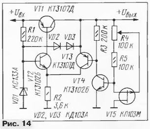
The use of a transistor analogue of a zener diode instead of the VD3 diode (see Fig. 9) does not exclude the simultaneous application of the recommendations described above for improving the R1VD1 ION. If you use a current stabilizer to power the ION, you can get Kst about 1000 even with a KS1ZZA zener diode. In this case, there is no need to regulate the stabilization current and change the voltage on the zener diode VD1, since this has little effect on the output voltage of the stabilizer. To prevent self-excitation in stabilizers of this type, it is enough to turn on oxide capacitors at the output of the stabilizer, with a capacity of several tens of microfarads, and ceramic, about 0,1 μF, capacitors. If this is not enough, a capacitor with a capacity from several hundred picofarads to several tens of nanofarads is connected between the terminals of the base and collector of the transistor VT3 (Fig. 13) (the minimum required capacitance depends on the power of the stabilizer). ST in battery-powered regulators is hardly worthwhile without a significant improvement in TKN, since the fluctuations in the output voltage associated with a change in ambient temperature will be much larger than those associated with a change in the supply voltage. In network power supplies, it is permissible to use circuits with a large KST, if this is dictated by the need to obtain minimal ripple of a stabilized voltage. It is possible to increase the stabilization coefficient to 1500 ... 3000 using an analogue of a zener diode on three transistors (Fig. 14).
Some parameters of such a stabilizer, tested with a load current of 20 mA at a limiting current of 70 ... 90 mA, are given in Table. 7.
Consumption current - no more than 0,6 mA, Rout. - about 0,1 Ohm, ΔUmin - no more than 0,14 V. The TCR of the stabilizer (Fig. 14) is almost completely dependent on the TCR of the Zener diode analogue and can reach -1,5 mV/°C. Using a FET with a lower cutoff voltage will slightly improve the TCR. With an increase in the reference voltage relative to UOTC (with a potentiometer in the source circuit), the TKN of the zener diode analogue shifts towards positive values. The same result can be obtained by reducing the current through the field-effect transistor VT5 by increasing the total resistance of resistors R4 and R5. Current stabilization (see Fig. 6, b or 6, c) of the Zener diode VD1 allows you to obtain a stabilization coefficient of more than 5000. In the absence of transistors with a high current transfer coefficient, especially in powerful stabilizers, a composite regulating transistor is used. On fig. 15 shows one such option. A stabilizer with a composite regulating transistor has one feature. In the absence of load current, the current consumed by it is negligible; at a load current close to the maximum, it almost does not differ from the current consumption of previous modifications of stabilizers.
For example, a variant of a powerful stabilizer with a regulating transistor KT837V (h21E \u120d 300): Kst \u500d \u0,1d XNUMX ... XNUMX, Rout. = XNUMX ohm, Uout. \u6,4d 1,9 V, Ilimit \u12d 300 A; at an input voltage of 1,0 V at idle, it consumes a current of no more than 30 μA. At a load current of XNUMX A, the current consumption increases to XNUMX mA. A variant of a low-power stabilizer with a limiting current of 80 mA (Kst = 500 ... 700, Rout = 1 Ohm), consumes no more than 60 μA at idle. At a load current of 25 mA, the current consumption increases to 400 μA. In table. 6 shows some other parameters of the two variants of stabilizers.
This is not limited to all options for upgrading the stabilizer taken as the basis (see Fig. 9) in order to increase efficiency and improve other parameters. In particular, in some cases, to reduce ΔUmin, it is useful to use parallel connection of several transistors with current-leveling resistors in the base circuits instead of one regulating transistor. Using microcurrent IONs, other types of stabilizers can also be successfully upgraded. The tables of characteristics of stabilizers given in the article are not samples of optimal calculation and guarantees of complete coincidence of the results when repeated due to the wide spread of parameters of zener diodes and field-effect transistors. These tables are useful for analyzing general trends in the development of stabilizers and can serve as a basis for their selection. Various stabilizer options are designed for a load current of 20 mA for easy comparison of the main parameters. For the same reason, most of the parameters were measured at UBX = 2U out. If necessary, stabilizers can be recalculated for a different load current. For example, in table. 6 and 8 show the parameters for building stabilizers for a load current of 2,5, 200 mA and 0,5 A. Since the circuit diagrams given in the article are quite universal, they, as well as in the tables, may lack specific information on any elements. In this case, they are chosen or calculated independently, guided by the general rules and recommendations contained in the article.
To improve the operation of stabilizers at elevated temperatures or when using transistors with high reverse collector current, we recommend connecting a resistor between the emitter and the base of the regulating transistor with a resistance of several units to several tens of kilo-ohms, depending on the power of the stabilizer. Despite the fact that the article describes stabilizers that claim to be economical, the specific efficiency value is not given anywhere, since this parameter depends on the specific ratio of the input and output voltage and varies over a wide range, increasing as the voltage at the battery terminals decreases. Literature
Author: V.Andreev, Togliatti
Artificial leather for touch emulation
15.04.2024 Petgugu Global cat litter
15.04.2024 The attractiveness of caring men
14.04.2024
▪ Car body will change stiffness in an accident ▪ TV for mobile phones: crazy growth expected ▪ Mindfulness enhances selfishness
▪ section of the website Basics of First Medical Aid (BFA). Selection of articles ▪ article Good riddance. Popular expression ▪ article What was the largest eruption in history? Detailed answer ▪ Eye injury article. Health care ▪ article Ink pencils. Simple recipes and tips ▪ article Lever scales. physical experiment
Home page | Library | Articles | Website map | Site Reviews www.diagram.com.ua |


 Arabic
 Bengali
 Chinese
 English
 French
 German
 Hebrew
 Hindi
Hindi Italian
 Japanese
 Korean
 Malay
Malay Polish
 Portuguese
 Spanish
 Turkish
 Ukrainian
 Vietnamese








 Leave your comment on this article: