|
|


 Arabic
 Bengali
 Chinese
 English
 French
 German
 Hebrew
 Hindi
Hindi Italian
 Japanese
 Korean
 Malay
Malay Polish
 Portuguese
 Spanish
 Turkish
 Ukrainian
 Vietnamese
|
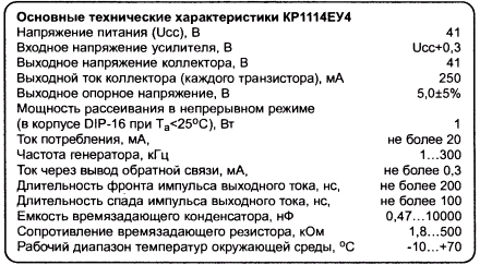
ENCYCLOPEDIA OF RADIO ELECTRONICS AND ELECTRICAL ENGINEERING Switching stabilizers on the PWM controller KR1114EU4. Encyclopedia of radio electronics and electrical engineering
Encyclopedia of radio electronics and electrical engineering / Surge Protectors At present, microcircuits (domestic and imported) are widely represented on the market, which implement a different set of PWM control functions for switching power supplies. Among microcircuits of this type, KR1114EU4 (producer ZAO Kremniy-Marketing, Russia) is quite popular. Its imported counterpart is TL494CN (Texas Instrument). In addition, it is produced by a number of companies under different names. For example, (Japan) produces the IR3M02 chip, (Korea) - KA7500, f. Fujitsu (Japan) МВ3759.
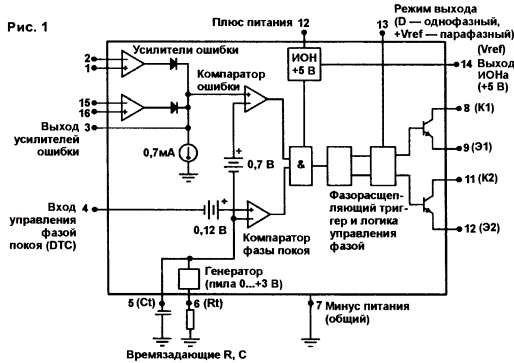
The KR1114EU4 (TL494) microcircuit is a PWM controller of a switching power supply operating at a fixed frequency. The structure of the microcircuit is shown in Fig.1.
On the basis of this microcircuit, it is possible to develop control circuits for push-pull and single-cycle switching power supplies. The microcircuit implements a full set of PWM control functions: reference voltage generation, error signal amplification, sawtooth voltage generation, PWM modulation, 2-stroke output generation, through current protection, etc. It is produced in a 16-pin package, the pinout is shown in fig. 2.
The built-in sawtooth voltage generator requires only two external components, Rt and Ct, to set the frequency. The frequency of the generator is determined by the formula:
To remotely turn off the generator, you can use an external key to close the RT input (pin 6) to the ION output (pin 14) or close the ST input (pin 5) to a common wire. The microcircuit has a built-in voltage reference (Uref=5,0 V) capable of providing up to 10 mA of current to bias external circuit components. The reference voltage has an error of 5% in the operating temperature range from 0 to +70°C. The block diagram of the pulse step-down stabilizer is shown in Fig.3.
The control element of the RE converts the input DC voltage UBX into a sequence of pulses of a certain duration and frequency, and the smoothing filter (choke L1 and capacitor C1 converts them again into an output DC voltage. Diode VD1 closes the current circuit through the throttle when the RE is turned off. With the help of feedback, the control circuit CS controls the regulating element in such a way that, as a result, the specified stability of the output voltage Un is obtained. Stabilizers, depending on the stabilization method, can be relay, pulse-frequency modulated (PFM) and pulse-width modulated (PWM). In PWM stabilizers, the pulse frequency (period) is a constant value, and their duration is inversely proportional to the value of the output voltage. Figure 4 shows pulses with different duty cycle Ks.
PWM stabilizers have the following advantages over other types of stabilizers:
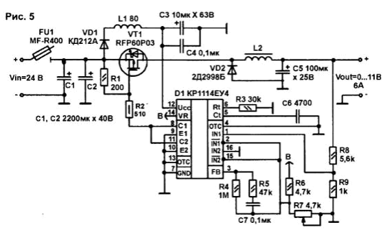
The only difference is that PWM circuits have a relatively complex control circuit. But the development of integrated circuits of the KR1114EU4 type, containing inside most of the SU nodes with PWM, can significantly simplify switching stabilizers. The diagram of a pulsed step-down stabilizer based on KR1114EU4 is shown in Fig. 5.
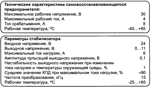
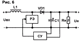
The maximum input voltage of the stabilizer is 30 V, it is limited by the maximum allowable drain-source voltage of the p-channel field effect transistor VT1 (RFP60P03). Resistor R3 and capacitor C5 set the frequency of the sawtooth voltage generator, which is determined by formula (1). From the reference voltage source (pin 14) D1 through the resistive divider R6-R7, part of the reference voltage is supplied to the inverting input of the first error amplifier (pin 2). The feedback signal through the divider R8-R9 is fed to the non-inverting input of the first error amplifier (pin 1) of the microcircuit. The output voltage is regulated by resistor R7. Resistor R5 and capacitor C6 carry out the frequency correction of the first amplifier. It should be noted that the independent output drivers of the microcircuit ensure the operation of the output stage in both push-pull and single-cycle modes. In the stabilizer, the output driver of the microcircuit is switched on in single-cycle mode. For this, pin 13 is connected to a common wire. Two output transistors (their collectors - pins 8, 11, emitters - pins 9, 10) are connected according to a common emitter circuit and operate in parallel. In this case, the output frequency is equal to the frequency of the generator. The output stage of the microcircuit through a resistive divider R1-R2 controls the regulating element of the stabilizer - field effect transistor VT1. For more stable operation of the stabilizer for powering the microcircuit (pin 12), an LC filter L1-C2-C3 is included. As can be seen from the diagram, when using KR1114EU4, a relatively small number of external elements is required. It was possible to reduce switching losses and increase the efficiency of the stabilizer due to the use of a Schottky diode (VD2) KD2998B (Unp=0,54 V, Uobr=30 V, lpr=30 A, fmax=200 kHz). To protect the stabilizer from overcurrent, a self-resetting fuse FU1 MF-R400 is used. The principle of operation of such fuses is based on the ability to sharply increase their resistance under the influence of a certain value of current or ambient temperature and automatically restore their properties when these causes are eliminated. The stabilizer has a maximum efficiency (about 90%) at a frequency of 12 kHz, and the efficiency at an output power of up to 10 W (Uout = 10 V) reaches 93%. Details and design. Fixed resistors - type S2-ZZN, variables - SP5-3 or SP5-2VA. Capacitors C1 C3, C5-K50-35; C4, C6, C7 -K10-17. Diode VD2 can be replaced by any other Schottky diode with parameters no worse than the above, for example, 20TQ045. The KR1114EU4 chip is replaced by TL494LN or TL494CN. Choke L1 - DM-0,1-80 (0,1 A, 80 μH). Inductor L2 with an inductance of about 220 μH is made on two annular magnetic cores stacked together. MP-140 K24x13x6,5 and contains 45 turns of wire PETV-2 01,1 mm, laid evenly in two layers around the entire perimeter of the ring. Two layers of varnished fabric are laid between the layers. LShMS-105-0.06 GOST 2214-78. Resettable fuse type MF-RXXX can be selected for each specific application. The stabilizer is made on a breadboard with dimensions of 55x55 mm. The transistor is mounted on a radiator with an area of at least 110 cm2. During installation, it is advisable to separate the common wire of the power unit and the common wire of the microcircuit, as well as to minimize the length of the conductors (especially the power unit). The stabilizer does not need to be adjusted with proper installation. The total cost of purchased radio elements of the stabilizer was about $ 10, and the cost of the VT1 transistor was $ 3 ... 4. To reduce the cost, instead of the RFP60P03 transistor, you can use the cheaper RFP10P03, but, of course, this will slightly worsen the technical characteristics of the stabilizer. A block diagram of a step-up type pulse parallel stabilizer is shown in Fig. 6.
In this stabilizer, the control element RE, operating in a pulsed mode, is connected in parallel with the load Rh. When the RE is open, the current from the input source (Ubx) flows through the inductor L1, storing energy in it. The diode VD1 at the same time cuts off the load and does not allow the capacitor C1 to be discharged through an open RE. The current in the load during this period of time comes only from the capacitor C1. At the next moment, when the RE is closed, the EMF of the self-induction of the inductor L1 is added to the input voltage, and the energy of the inductor is given to the load. In this case, the output voltage will be greater than the input. In contrast to the step-down stabilizer (Fig. 1), here the inductor is not a filter element, and the output voltage becomes greater than the input voltage by an amount determined by the inductance of the inductor L1 and the pulse duty cycle of the RE control element.
A schematic diagram of a switching boost regulator is shown in Fig. 7.
It uses basically the same electronic components as in the buck regulator circuit (Fig. 5). Ripple can be reduced by increasing the capacitance of the output filter. For a "softer" start, a capacitor C1 is connected between the common wire and the non-inverting input of the first error amplifier (pin 9). Fixed resistors - S2-ZZN, variables - SP5-3 or SP5-2VA. Capacitors C1 C3, C5, C6, C9 - K50-35; C4, C7, C8 - K10-17. Transistor VT1 - IRF540 (n-channel field-effect transistor with Usi = 100 V, lc = 28 A, Rsi = 0,077 Ohm) - is installed on a radiator with an effective surface area of at least 100 cm2. Choke L2 - the same as in the previous circuit. It is better to turn on the stabilizer for the first time at a small load (0,1 ... 0,2 A) and a minimum output voltage. Then slowly increase the output voltage and load current to the maximum values. If the step-up and step-down stabilizers operate from the same input voltage Uin, then their conversion frequency can be synchronized. To do this (if the step-down stabilizer is the leader, and the step-up slave) in the step-up stabilizer, you need to remove the resistor R3 and the capacitor C7, close pins 6 and 14 of the D1 chip, and connect pin 5 of D1 to pin 5 of the D1 chip of the step-down stabilizer. In a boost-type stabilizer, the inductor L2 does not participate in smoothing the output DC voltage ripple, therefore, for high-quality filtering of the output voltage, it is necessary to use filters with sufficiently large values of L and C. This, accordingly, leads to an increase in the mass and dimensions of the filter and the device as a whole. Therefore, the specific power of the step-down stabilizer is greater than the step-up. Author: S. Shishkin, Sarov, Nizhny Novgorod Region
Artificial leather for touch emulation
15.04.2024 Petgugu Global cat litter
15.04.2024 The attractiveness of caring men
14.04.2024
▪ Comparator Texas Instruments TLV3691IDCKR
▪ site section Field strength detectors. Article selection ▪ article Cinema is the only consolation in a woman's life. Popular expression ▪ article How does scuba gear work? Detailed answer ▪ article CTO Administrator. Job description
Comments on the article: Alexander In Fig. 1 (E2) should be 10pin, 12pin is erroneously indicated Paul Alexander is right. Really (E2) on output 10, not 12. And there can't be two 12th outputs. Yes, with different functions. Be more attentive to such things, in such cases. Don't throw a cigarette butt. Yes, this can not be done anywhere and anyhow. Sorry.
Home page | Library | Articles | Website map | Site Reviews
www.diagram.com.ua |


 Leave your comment on this article: