|
|


 Arabic
 Bengali
 Chinese
 English
 French
 German
 Hebrew
 Hindi
Hindi Italian
 Japanese
 Korean
 Malay
Malay Polish
 Portuguese
 Spanish
 Turkish
 Ukrainian
 Vietnamese
|
ENCYCLOPEDIA OF RADIO ELECTRONICS AND ELECTRICAL ENGINEERING Power regulators on a thyristor-transistor generator. Encyclopedia of radio electronics and electrical engineering
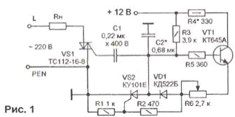
Encyclopedia of radio electronics and electrical engineering / Regulators of current, voltage, power With the advent of thyristors, a convenient opportunity appeared to regulate the power of the load operating from alternating voltage. Many different schemes have been invented for controlling thyristor switches that switch the load. For example, in the power regulator circuit in Fig. 1, the power triac is controlled by a thyristor-transistor key generator, discussed in previous articles [1, 2].
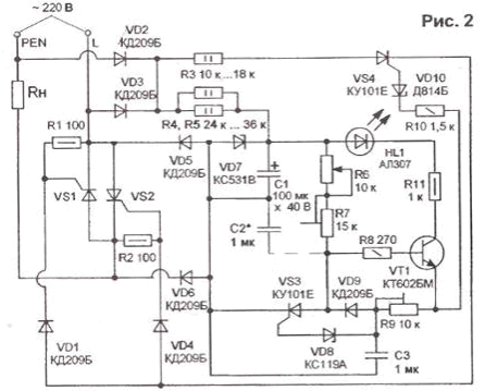
The device allows, with careful selection of capacitors C1 and C2, to achieve smooth adjustment of the load power Rh using R6. The device works as follows. When the power is turned on (12 V for control circuits and 220 V for load), capacitors C12 and C1 are charged from the "+" source of 2 V, and a positive bias based on transistor VT1 opens its collector-emitter junction, through which resistors R2, R6 voltage enters the control electrode of the thyristor VS2. At a current greater than the holding current, the thyristor VS2 opens and discharges the capacitor C1 through the control electrode of the triac VS1, opening it. When the thyristor VS2 is closed, the capacitor C1 is charged, and the charge current flows through the control electrode of the triac VS1 in the opposite direction. The opening angle VS1 is determined by the opening and closing times of the thyristor VS2, depending on the capacitances of capacitors C1, C2 and the resistance of the regulator R6. When the resistance R6 changes, the angle shifts. In the thyristor power controller circuit (Fig. 2), the supply voltage is supplied to the master oscillator circuit in a transformerless circuit.
Excess voltage is quenched by ballast resistors R4 and R5. The control voltage (30 V) is stabilized by the Zener diode VD7. Such a power supply has a "falling" characteristic, i.e. As the load current increases, the voltage drops. The short circuit current of the source is 15...18 mA and depends on the resistances R4 and R5. The opening angle of the thyristors VS1, VS2 is determined by the opening moment of the transistor VT1 and the voltage at the emitter, at which the breakdown of the zener diode VD10 occurs through the control electrode of the thyristor VS4. The switching time of the transistor VT1 is set by the regulator R6 and the capacitances of the capacitors C3 and C2 (the latter may not even be set). Thyristors in the considered circuits are taken with holding currents of 2 ... 8 mA, but they can "swing" at currents up to 12 mA due to larger capacitors. Therefore, to increase the sensitivity of the switching thyristor VS3, the protective resistor between the cathode and the control electrode can be omitted or its resistance can be increased (more than 2 kOhm). The load power is adjusted with a variable resistor R6 of the type PPP-43, and the resistors R7 and R9 serve as construction resistors. After adjustment, they can be changed to permanent ones. Thyristors VS1, VS2 - impulse type. KU202 or similar with a voltage class of at least 400 V. Transistor VT1 - KT645, KT815, KT602, KT940, capacitors C2 C3 - K73-17. A good power regulator is obtained according to the scheme in Fig. 3.
Here, an optocoupler VU1 of the AOU103V1 type is introduced into the thyristor-transistor generator control circuit. The HL1 LED in the control circuit of the VS3 thyristor performs the function of a zener diode and at the same time serves as a control element during commissioning. The principle of operation of the device is similar to the previous scheme. The regulator is assembled on a printed circuit board, the drawing of which is shown in Fig.4.
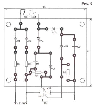
A simple power regulator using dinistors is shown in Fig. 5.
It provides a regulation voltage of 30 ... 220 V. The opening angle of the thyristors VS2, VS3 is determined by the charge time of the capacitors C1 and C2 to the breakdown voltage of the dinistors VS1 and VS4, which is set by the resistance R5. For smooth regulation, it is necessary to select thyristors VS2 and VS3 with the same opening currents, although this is quite laborious. Simplified, it is necessary to select thyristors with the same resistance of the cathode-control electrode circuits. The device can be used to control the brightness of incandescent lighting lamps, but at a voltage of less than 30 V, voltage instability is observed and flickering of the lamps may occur. Therefore, it is worth limiting the range of change in the resistance of the regulator R5 or combine it with the switch SA1, which turns off the control circuit. The printed circuit board of the device is shown in Fig.6.
A full-wave power controller with a control circuit based on one thyristor is shown in Fig. 7.
Load Rh is connected to an AC voltage source through a rectifier bridge, and the second diagonal of the bridge is short-circuited through a thyristor controlled switch VS2. In the control circuit, instead of the KN102 dinistor, its analog, assembled on a pulsed thyristor, is included. KU101E and the zener diode VD5 included in the circuit of its control electrode. Using this circuit, you can control the load, which is the primary winding of the network transformer (for 220 V) with a voltage regulation range of 160 ... 220 V. Such regulation effectively changes the output voltage of the secondary winding of this transformer. It is not recommended to set the voltage on the primary winding of the transformer less than 160 ... 170 V, since with a decrease in current through the control electrode of the thyristor switch, it can work unstably. Literature
Authors: A. Alekseev, V. Alekseev Perm.
Machine for thinning flowers in gardens
02.05.2024 Advanced Infrared Microscope
02.05.2024 Air trap for insects
01.05.2024
▪ AA/AAA batteries from hybrid car batteries ▪ Drone will find a person by voice ▪ Nanocomposite on graphene and silicon will improve lithium-ion batteries
▪ section of the site Electrician's Handbook. Article selection ▪ database article. Lecture notes ▪ article What are amphibians? Detailed answer ▪ article Occupational safety of employees of housing and communal services ▪ article Ivory whitening. Simple recipes and tips ▪ article Unfolding newspaper. Focus Secret
Home page | Library | Articles | Website map | Site Reviews
www.diagram.com.ua |


 Leave your comment on this article: