|
|


 Arabic
 Bengali
 Chinese
 English
 French
 German
 Hebrew
 Hindi
Hindi Italian
 Japanese
 Korean
 Malay
Malay Polish
 Portuguese
 Spanish
 Turkish
 Ukrainian
 Vietnamese
|
ENCYCLOPEDIA OF RADIO ELECTRONICS AND ELECTRICAL ENGINEERING Automatic discharge device for batteries. Encyclopedia of radio electronics and electrical engineering
Encyclopedia of radio electronics and electrical engineering / Chargers, batteries, galvanic cells The device offered to the attention of readers is designed to automatically discharge Ni-Cd or NI-MH batteries of AA or AAA size to a predetermined voltage. The device has a light indication of operating modes and does not require an additional power source, since it is powered directly from a discharged battery. It is known that the service life and guaranteed capacity of Ni-Cd and Ni-MH batteries depend on how well they are used. It is also well known that one of the reasons for the deterioration of the "health" of the battery is the memory effect inherent in nickel-based batteries. The memory effect is a loss of battery capacity that develops as a result of charging an incompletely discharged battery. This effect is most pronounced in Ni-Cd batteries, for Ni-MH, according to manufacturers, its manifestation is insignificant. But as practice shows, when using Ni-MH batteries, one should not neglect such an "insignificant" manifestation. An effective and affordable method of combating the memory effect is to prevent its manifestation, which consists either in completely discharging the battery to a safe residual voltage before each charge or in conducting periodic training. Training is understood as carrying out several repetitive charging cycles followed by discharging to a voltage of 1,05 ... 1,1 V. The frequency of training for Ni-Cd batteries is once a month, for Ni-MH - once every two months, more often training has an adverse effect on the condition of the battery due to its accelerated wear. Modern universal chargers (chargers), built on the basis of specialized controllers, immediately before the start of the charging process, as a rule, pre-discharge the batteries to a safe voltage, thereby preventing the development of the memory effect. But the cost of such memory is quite high. Therefore, in the presence of simple memory, they can be supplemented by the proposed bit device. A diagram of such a device is shown in Fig. 1.
A boost-DC converter is assembled on the DA1 chip, which generates a voltage sufficient for the operation of the remaining elements of the device. By connecting pin 2 of the DA1 chip with a negative power line, the output voltage of the converter is selected to be 5 V. An adjustable load equivalent is assembled on a powerful bipolar transistor VT1 and a variable resistor R2. The discharge current adjustment range is 0,07 ... 1 A (taking into account the current consumed by other components of the device). The field-effect transistor VT2 is used to connect the dummy load to the battery being discharged, the transistor VT3 is used to control the supply voltage of the converter, and the button SB1 is to start the device. A comparator is assembled on the op-amp DA2.2, which monitors the lower threshold voltage of the battery (1,05 ... 1,1 V). On OUDA2.1 and LED HL2-indicator, signaling that. that the battery voltage exceeds 1,2 V, it serves as a rough estimate of the degree of battery discharge at a given value of the discharge current. On resistors R5-R7, a voltage divider is made, which forms the thresholds for the operation of the comparators. If the battery voltage is above the lower threshold, then after starting the device by briefly pressing the SB1 button, the output of the op-amp DA2.2 will set to a high level, this will open the transistor VT3 and allow the device to remain on after the button is released. Simultaneously with the transistor VT3, the transistor VT2 will open, and the equivalent load will be connected to the battery. The glow of the HL1 LED indicates the ongoing discharge of the battery. If at the same time its voltage exceeds 1,2 V, the HL2 LED will light up. When the battery voltage becomes less than the lower threshold, at the output of the op-amp DA2.2, the high level will change to low, the transistors VT2, VT3 will close, and therefore the load dummy and the voltage converter will be turned off, the HL1 LED will turn off. The use of separate voltage supply to the load dummy and other nodes is due to the need to exclude the effect of a change in the discharge current on the operation of the device. So, if only one switching transistor were used, the decrease in the discharge current that occurs in the process of discharging the battery would lead to the departure of the comparator thresholds due to a change in the voltage difference between the negative terminal of the battery and the negative supply line of the op-amp. Most of the parts are mounted on a printed circuit board made of one-sided foil fiberglass 1 mm thick (Fig. 2).
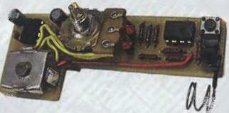
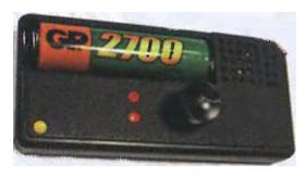
The board is designed to install fixed resistors MLT, S2-33, a variable resistor - SPZ-4AM, it is mounted on the front panel of the device and connected to the board with insulated wires. Oxide capacitors - small-sized imported, C3 - ceramic K10-17 or imported. The voltage converter MAX756 can be replaced by a domestic analogue - KR1446PN1, dual op-amp KA358 - with op-amp KR1040UD1, LM358, RS1251. The KT817A transistor can be replaced with any of the KT817 series in a plastic case, it is equipped with a self-made aluminum heat sink with an area of about 3,5 cm2, and the KP505A field-effect transistors are replaceable with KP505B. KP505V. BSS295. Diode VD1 - any of the KD521, KD522, KD102 series. KD103 or imported 1N4148. LEDs - any small-sized ones with a lens diameter of 3 mm and sufficient brightness at a current of 1 mA. Choke-import EC24 inductance 22...100 mkH. Button SB1 - with self-return TS-0403 5 mm high and 1,5 mm pusher length. The appearance of the mounted board is shown in fig. 3, and the entire device - in Fig. 4. It has a plastic case with overall dimensions of 83x38x13mm. To facilitate the temperature regime, ventilation holes are made in the case.
When adjusting, the thresholds for the operation of comparators are set by a selection of resistors R5-R7. The variable resistor engine can be equipped with a pointer, and a discharge current scale can be placed on the case, which is calibrated using a milliammeter. Author: Kelekhsashvili V.
Machine for thinning flowers in gardens
02.05.2024 Advanced Infrared Microscope
02.05.2024 Air trap for insects
01.05.2024
▪ Project Jacquard for creating electronic clothing ▪ Seat belt that unfastens in the water ▪ Alien star discovered in the Milky Way ▪ Optimists are not afraid of a heart attack
▪ site section Clocks, timers, relays, load switches. Article selection ▪ Article by Sextus Propertius. Famous aphorisms ▪ article Who first invented the alphabet? Detailed answer ▪ article Nokia HS-23 headset repair. Encyclopedia of radio electronics and electrical engineering ▪ article Coin in a handkerchief. Focus Secret
Comments on the article: Be Put a rezyuk for discharge.
Home page | Library | Articles | Website map | Site Reviews
www.diagram.com.ua |


 Leave your comment on this article: