|
|


 Arabic
 Bengali
 Chinese
 English
 French
 German
 Hebrew
 Hindi
Hindi Italian
 Japanese
 Korean
 Malay
Malay Polish
 Portuguese
 Spanish
 Turkish
 Ukrainian
 Vietnamese
|
ENCYCLOPEDIA OF RADIO ELECTRONICS AND ELECTRICAL ENGINEERING Nokia HS-23 headset repair. Encyclopedia of radio electronics and electrical engineering
Encyclopedia of radio electronics and electrical engineering / Mobile telephony Somehow, a headset for the phone "Nokia HS-23" fell into my hands in a faulty condition. At first there were doubts, but is it worth it to repair this product at all? But the ease of disassembly, the relatively high price of such a simple accessory and "sport interest" decided the matter.
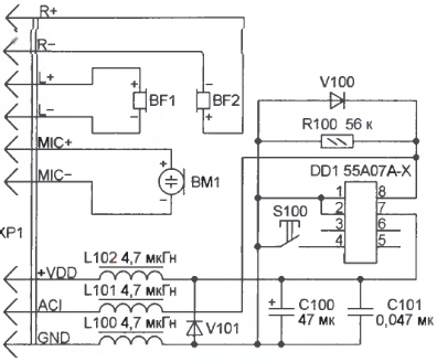
Since there was no information about the headset, it was decided to draw up a schematic diagram by examining the printed circuit board of this product and the inscriptions on it. The circuit thus obtained is shown in Fig. 1 The positional designations of the button, chokes, capacitors, resistors and diodes, as well as the names of the circuits correspond to the markings on the board. As the study of several headsets for Nokia HS-23 phones showed, they are all assembled according to the same scheme, although sometimes they differ in the shape of the case, the dimensions of the printed circuit board, and the arrangement of elements on it. A specialized microcircuit with the inscription 55A07A-X ensures that the headset is identified as a "branded" one when it is connected to the phone, transmitting a code pulse sequence through the ACI (accessory identification) circuit. In a similar way, she sends a message to the phone about pressing the S100 button on the headset. The supply voltage (VDD) is supplied to the chip from the phone.
Unfortunately, no information about the structure and content of the transmitted codes could be found. The appearance of the connector that connects the headset to the phone is shown in fig. 2. The purpose of its contacts and the color of the connecting wires coming from them to the board, we managed to determine by "dialing" with a multimeter. R+ (dark brown), R- (brown with black stripes) - right headset;
Repair of the headset should begin with a careful examination of the board for cracks, chips on the elements, breaks in the printed conductors and wires of the cable going to the connector. If the phone does not respond to the headset connection, it is necessary to check the presence of supply voltage between pins 1, 2 and 7 of the microcircuit. Its absence can be caused not only by breaks in the wires + VDD or GND in the connecting cable, but also by an open inductor L102, a breakdown of the diode V101, too much leakage current of capacitors C100, C101. If there is supply voltage, you need to check with an oscilloscope the presence of a pulse train board on the ACI contact pad at the moment the XP1 connector is connected to the phone. The high and low levels of the pulses should be close to the supply voltage of the microcircuit and to zero, respectively. The absence of pulses indicates a break in the L101 inductor or printed conductors, a breakdown of the V100 diode. Of particular note is the case when there are pulses, but their high level is too small or the low level is noticeably higher than zero. This may indicate both a malfunction of the microcircuit and the presence of leaks on the surface of the printed circuit board due to poor flushing of flux residues after installation. As a rule, rinsing the board with alcohol is sufficient to eliminate leaks. But sometimes you have to solder the chip and wash the board under it. In some cases, it helps to clean the gaps between the contact pads with a sharp needle, to which the microcircuit leads are soldered. This must be done very carefully so as not to damage the printed wiring. With a faulty microcircuit (it is almost impossible to find a replacement for it), unfortunately, it will not be possible to repair the headset. The loss of sound in one or both headphones or the fact that the interlocutor does not hear the words spoken in front of the microphone is most often to blame for breaks in the wires of the connecting cable. They happen, as a rule, in places where the cable is often kinked near the connector, headset case or headphones. Breaks inside a non-separable connector cannot be repaired. Fortunately, they don't happen often. Wire breaks near the headset case are easily repairable. Cut and remove part of the wire between the break and the contact pad on the board. It is not recommended to strip the end of the remaining serviceable wire, this threatens with a new break. It is better to put it on an aspirin tablet and use a clean, slightly overheated soldering iron to remove the insulation from the end of the wire 1 ... 1,5 mm long and tin it. It remains to solder the wire to the contact pad. Damaged headphones can be replaced with any suitable, for example, from an MPXNUMX player. The wires of new phones are cut to the desired length and soldered to the pads of the printed circuit board instead of the faulty ones. To further fix the wires inside the headset case, you can use hot melt adhesive. Publication: radioradar.net
Artificial leather for touch emulation
15.04.2024 Petgugu Global cat litter
15.04.2024 The attractiveness of caring men
14.04.2024
▪ Ultra-fast Samsung PM1725 and PM1633 SSDs ▪ Elusive ultralight oxygen discovered ▪ Emergency power supply of the LED lamp up to 3 hours ▪ Creating the Perfect Chocolate Texture
▪ site section Power Amplifiers. Article selection ▪ article History of psychology. Lecture notes ▪ article Which birds dig holes? Detailed answer ▪ article Monitoring the effectiveness of labor protection ▪ article A simple way of tinning. Simple recipes and tips ▪ article Bending organic glass. Encyclopedia of radio electronics and electrical engineering
Home page | Library | Articles | Website map | Site Reviews
www.diagram.com.ua |


 Leave your comment on this article: