|
|


 Arabic
 Bengali
 Chinese
 English
 French
 German
 Hebrew
 Hindi
Hindi Italian
 Japanese
 Korean
 Malay
Malay Polish
 Portuguese
 Spanish
 Turkish
 Ukrainian
 Vietnamese
|
ENCYCLOPEDIA OF RADIO ELECTRONICS AND ELECTRICAL ENGINEERING Charger with SHI current regulation. Encyclopedia of radio electronics and electrical engineering
Encyclopedia of radio electronics and electrical engineering / Chargers, batteries, galvanic cells The charger control unit is a pulse generator assembled on the elements DD1.1 and DD1.2 (see the diagram in Fig. 1) and allows you to adjust the duty cycle of the pulses, a buffer amplifier - an inverter on the elements DD1.3 and DD1.4 and a switching regulator element - field effect transistor VT1. With the values \u13b\uXNUMXbof the elements indicated on the diagram, the generator frequency is about XNUMX kHz. Since the resistance of the open channel of the transistor VT1 is very small (0,017 Ohm) and it works in switching mode, with a charging current of up to 5 A, the transistor practically does not heat up - the dissipated thermal power does not exceed 0,55 W. A network transformer with an overall power of 150 W with a secondary winding providing a constant voltage of 16 ... 17 V on the capacitor C1 and a charging current of up to 6 A was used as a step-down transformer.
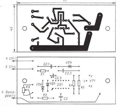
The rectifier bridge is assembled on Schottky diodes, VD1 is a dual SBL4045PT, and VD2 and VD3 are single 10TQ045. If the secondary winding of the network transformer is wound with a tap from the middle, the number of diodes in the rectifier and the heat dissipation from them can be halved. Structurally, the charger is shown in the photo fig. 2. The control unit is assembled on a printed circuit board made of fiberglass with a thickness of 1 mm. The rectifier diodes are mounted on a rigid aluminum alloy plate screwed to a 160x45mm molded pin heatsink. The diodes are attached to the plate through insulating spacers made of thin mica coated with a heat-conducting paste. The heat sink is screwed to the rear wall of the device case.
The VT1 transistor is mounted on a small (50x50x1 mm) plate made of copper, brass or aluminum alloy, attached with two screws to the printed circuit board of the control unit. The drawing of the board is shown in fig. 3. incandescent indicator lamp EL1 - MH26-0.12, (26 V, 0,12 A), ammeter RA1 - M476 / 2 from household tape recorders, shunt R6 - copper winding wire wound on a mandrel with a diameter of 8 mm. PEV-2 1,5, number of turns - 16 (resistance - about 0,1 Ohm). The full deviation of the ammeter needle with a shunt is at a current of 10 A. Capacitor C1 is imported, and C2 can also be assembled from two K73-17 with a capacity of 2,2 microfarads connected in parallel, or use an oxide capacitance of 10 microfarads for a voltage of 16 V (corresponding holes included in the fee).
The dimensions and weight of the charger can be significantly reduced by using the so-called "electronic transformer" to lower the mains voltage, which is used to power halogen lamps with a voltage of 12 V. It is a high-frequency transistor converter with a transformer output (it is this constructive version of the charger shown in the photo Fig. 2. I used a 150 W TASCHIBRA electronic transformer with an output voltage of 12 V. The secondary winding of its output transformer, wound on a ferrite magnetic core, contains 9 turns of a bundle of four enameled wires with a diameter of 1 mm (the cross section of the bundle is approximately 3 mm2). To work in the charger, the transformer must be subjected to a simple revision. To do this, it is carefully unsoldered from the board, the outer insulation is removed and the secondary winding is wound in the same direction with a similar bundle of four of the same wires with three more turns, which are connected in series with the existing winding. The place on the frame allows you to perform this operation without disassembling the magnetic circuit (it is glued together). After completion, the transformer is soldered into the board in its original place. Now the output voltage on the filter capacitor C1 rises to 17 V at a maximum charging current of 5,5 A (for the ST-55 battery). When using an electronic transformer, the oxide capacitor C1 should be replaced with another one with a capacity of 10 microfarads for a nominal voltage of at least 250 V, by connecting several K73-17V capacitors with a total capacity of 1-2 microfarads for a nominal voltage of at least 250 V each. The described control unit can be used in lighting and heating devices to change the rotational speed of collector motors. In this case, the supply voltage of the devices can be varied over a wide range, determined by the maximum allowable parameters for the switching transistor and, of course, the rectifier. In particular, the IRFZ46N transistor used in the node has a maximum power dissipation of 107 W, a maximum current through the channel of 53 A, a maximum drain-source voltage of 55 V. It can be replaced by an IRFZ44N transistor. The proposed device allows you to adjust the power from zero to the maximum value, and the control transistor does not need efficient heat removal when the load current increases to 5 A. Author: Tsypylov Yu.
Artificial leather for touch emulation
15.04.2024 Petgugu Global cat litter
15.04.2024 The attractiveness of caring men
14.04.2024
▪ Accurate frost forecast with AI ▪ Honest reward enhances memory ▪ Control of phonons with photons of light
▪ section of the site Household electrical appliances. Selection of articles ▪ article Lighting as a component of video filming. video art ▪ article How do flying dragons fly? Detailed answer ▪ article Switchable Gain Amplifier. Encyclopedia of radio electronics and electrical engineering
Home page | Library | Articles | Website map | Site Reviews
www.diagram.com.ua |


 Leave your comment on this article: