|
|


 Arabic
 Bengali
 Chinese
 English
 French
 German
 Hebrew
 Hindi
Hindi Italian
 Japanese
 Korean
 Malay
Malay Polish
 Portuguese
 Spanish
 Turkish
 Ukrainian
 Vietnamese
|
ENCYCLOPEDIA OF RADIO ELECTRONICS AND ELECTRICAL ENGINEERING Calculation of low-power power transformers. Encyclopedia of radio electronics and electrical engineering
Encyclopedia of radio electronics and electrical engineering / Power Supplies Power transformers are usually divided into two classes:
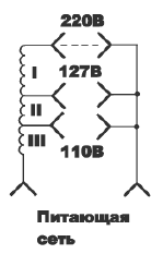
These transformers are calculated using two different methods. The problem arises when it is necessary to calculate a transformer with a power of 500 to 5000 W, when the method for calculating radio engineering transformers is no longer applicable, and the method for calculating electrical transformers is not yet applicable. In this case, the transformer is calculated twice, according to each of the methods, and its winding data and core cross section are chosen as the average of those obtained in these two calculations, and then refined experimentally. The given calculation method is used to calculate power transformers for low-power radio equipment, which are powered by a 110, 127, 220 V mains with a frequency of 50 Hz. There are two main approaches to the calculation of radio engineering transformers: copper optimization; hardware optimization. Accordingly, in the first case, a transformer of minimum cost is obtained, and in the second - of minimum weight. The minimum weight is very important for airborne or portable equipment. Transformer magnetic circuit For transformers of the minimum cost, sheet electrical steel grades E31, E41 with a plate thickness of 0,35, 0,5 mm is used. For transformers of minimum weight - steel grades E310, E320, E330. The design of the core (magnetic circuit) of the transformer can be divided into armored, rod, toroidal. Rod magnetic circuits are used in high-power transformers, as they improve cooling. Toroidal magnetic circuits allow better use of the magnetic properties of the material and create a much weaker external magnetic field than other cores. The magnetic core of the transformer can be made of stamped plates or wound from strips. The advantage of magnetic cores from stamped plates is that they can be made even from very fragile materials, but with good magnetic properties. The advantage of twisted magnetic circuits is the full use of the properties of electrical steel, ease of manufacture and small production waste. Transformer windings As a rule, the winding is wound on a frame made of a dielectric material - plastic, electric cardboard, etc. Sometimes, to reduce the external dimensions of the transformer, frameless winding on the sleeve is used. According to the design of the frame, the transformer can have cylindrical windings (in this case, the windings are wound one on top of the other) or biscuit (in this case, each winding is wound on a section reserved for it, starting from the transformer core). As a rule, windings containing many turns of thin wire are placed closer to the core of the transformer in order to reduce their active resistance and losses in them. Therefore, the network winding, as a rule, is wound on the frame first. The winding of wire on the coil of a transformer can be done in regular layers, or randomly "bulk". In any case, it is desirable to lay insulation between the layers of the winding to prevent interlayer short circuits. Interwinding insulation is also laid in the coil to prevent breakdown between adjacent windings. To increase the electrical insulation and protection of the transformer windings, they are impregnated with special compounds. Primary winding Power transformers are often required to operate on voltages of 110, 127 and 220 V. In this case, its primary winding can be made as shown in Fig. 1.
The disadvantage of this scheme is the increase in copper consumption and the complexity of the manufacture of the transformer due to the use of wires of different sections for winding windings I, II and III. Therefore, the scheme shown in Fig. 2 is more often used.
When connected to a 127 V network, the jumpers are set to position "2" and windings 2-3 and 4-5 are connected in parallel, and when connected to a 220 V network, the jumper is set to position "1" and all windings are connected in series. To carry out the calculation, the following must be specified:
As a result of the calculation, determine:
The transformer is a device that operates in an alternating current network, therefore, when calculating it, the effective values of alternating current and alternating voltage are used. Calculation sequence 1. Find the total power of the secondary windings at rated load: P2=I1U1+I2U2+...InUn. Where In and Un are the current and voltage on the nth winding, respectively. The overall power of the transformer is determined taking into account the efficiency (ηtr) (Table 1). Ptr=P2/ηtr, where ηtr - efficiency. Table 1
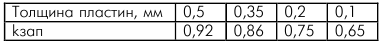
2. Select the maximum allowable values of current density ∆ and magnetic induction B. The value of magnetic induction for transformers with a rod and armored magnetic circuit is indicated in Table 1. When using twisted magnetic cores from cold-rolled electrical steels, the maximum induction value can be increased by 1,31,6-XNUMX times. 3. Determine the minimum allowable cross-sectional area of the magnetic circuit: Ssec=700[(aPtr)/(fB∆)]0,5 (cm2), where a is a coefficient of 4,5-5,5 for the lowest cost transformers and 2-3 for the lowest weight transformers; Ptr - transformer power, W; . - power supply frequency, Hz; B - the maximum value of the magnetic induction, Gs; ∆ - allowable current density, A/mm2. For the lowest cost transformers operating on a 50 Hz network, a maximum inductance of 10000 gauss and a current density of 3 A/mm are usually assumed.2. This simplifies the formula: Ssec=1,3(Ptr)0,5 (cm2). The cross section of the magnetic circuit is determined taking into account the fill factor of the section with steel: S'sec=Ssec/kzap. The values of kzap depending on the thickness of the plates of the magnetic circuit are given in Table 2. Table 2
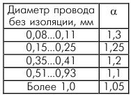
4. Determine the dimensions of the magnetic circuit. For an armored magnetic circuit, its type and dimensions can be selected from tables V.1 and V.2 [1]. Having chosen the type of plates, the thickness of the magnetic circuit Y1 is determined by the formula: Y1=S'sec/Y, where Y is the width of the central part of the plate for the armored magnetic core. The Y1/Y ratio should not exceed 2-3. Otherwise, there is a noticeable increase in the stray field of the transformer torus, and you will need to select larger plates. For a toroidal magnetic circuit, the inner (D1) and outer (D2) diameters are determined by the formulas: D1=(1,75Ssec/σα)0,5, D2=2Ssec/bk, where σ is the coefficient of filling the window with copper (usually 0,23-0,25); b is the height of the magnetic circuit, cm. 5. Determine the number of turns per volt in the transformer: ω=2,2х107/fBSsec When the transformer is operated from a network with a frequency of 50 Hz and a maximum induction of 10000 gauss, the formula takes the form: ω=45/Ssec. The number of turns in each winding is determined by multiplying the value obtained by the voltage on each particular winding. In this case, the number of turns of the secondary windings should be increased by 3 ... 5% (depending on the current consumed from the winding) in order to take into account the voltage drop across the winding resistance. 6. Determine the wire diameters for each of the windings: d=1,13(I/∆)0,5, where I is the maximum current in the winding; ∆ - current density in the transformer, A/mm2. You can also use the approximate formula: d=0,7(I)0,5. 7. Checking the placement of windings on the frame of a transformer with an armored core. Number of turns in one winding layer ω=(h−2(δ+2))/(αdout), where h is the height of the transformer frame window; δ is the thickness of the material of the transformer frame; diz - diameter of the winding wire with insulation; α - leakage coefficient (Table 3). Table 3
The number of layers of each of the windings Nsl=ω/ωsl, where ω is the number of winding turns; ωsl is the number of turns in the layer of this winding. In order for all windings to be placed in the transformer window, the following condition must be met: B>δ+Σδexchange+Σδpr, where Σδobm is the total thickness of all windings; Σδpr - the total thickness of all gaskets between the windings; B - window width. If the windings, together with the insulation, take up more space than the window of the selected core, then the size of the magnetic circuit plates should be increased and the transformer recalculated. References:
Author: A.Yu. Saulov
Machine for thinning flowers in gardens
02.05.2024 Advanced Infrared Microscope
02.05.2024 Air trap for insects
01.05.2024
▪ SANYO Moves to OLED Displays ▪ Solid state optical nanodrive ▪ The popularity of ultraportable laptops is growing
▪ section of the site Protection of electrical equipment. Article selection ▪ article History of psychology. Crib ▪ article Who are Quakers? Detailed answer ▪ article Electric car driver. Standard instruction on labor protection
Home page | Library | Articles | Website map | Site Reviews
www.diagram.com.ua |


 Leave your comment on this article: