|
|
ENCYCLOPEDIA OF RADIO ELECTRONICS AND ELECTRICAL ENGINEERING Domino game indication. Encyclopedia of radio electronics and electrical engineering
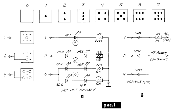
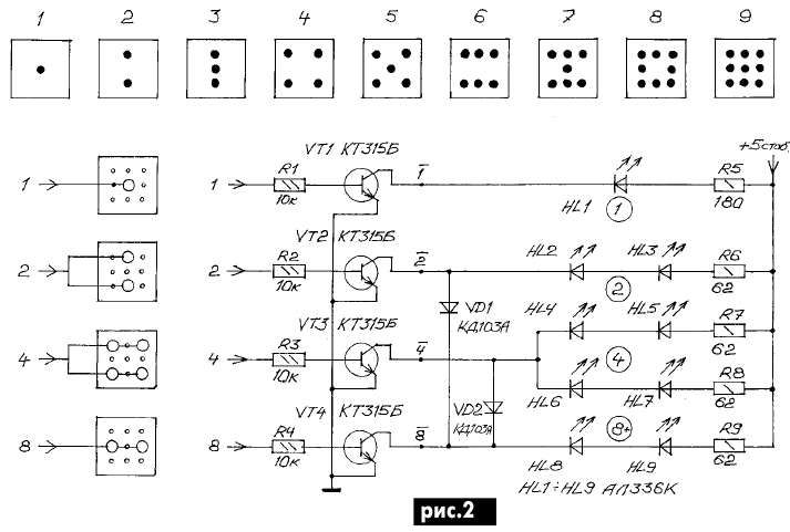
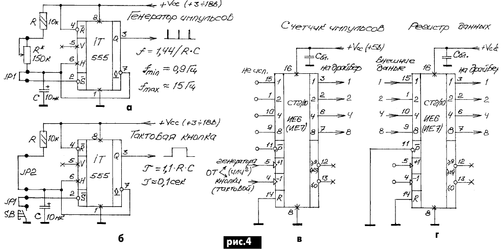
Encyclopedia of radio electronics and electrical engineering / Indicators, sensors, detectors Sometimes it is necessary to build a digital indicator for a small number of digits (1 or 2), information from which must be read from a large distance, from different directions and positions of the observer, or when the indicator itself is difficult to move (for example, tilts or turns over). Such indicators are convenient for vehicles, security systems, where they can show the current state of the system (degree of readiness, etc.). Traditional seven-segment indicators are of little use here, since for fast and error-free reading of Arabic numerals, their horizontal orientation is necessary, and they are poorly read in an inverted or oblique form. When only one segment is extinguished, the image is almost unreadable. The creators of popular games faced similar problems at one time. After all, players need to quickly and accurately read the current information inscribed on gaming accessories. The position of the gaming accessories on the table can be arbitrary, but the information must be read unambiguously from any place at the gaming table. The most successful and time-tested principle was the principle of a stylized mnemonic representation of numbers with contrasting dots against the background of a square familiarity, used in the popular game "Domino". Bones for the game "Domino" are bars, the front side of which is divided into two square-shaped familiar spaces, each of which contains numbers from "0" (empty) to "6" (in the form of six dots). In a similar way, the faces of the throwing dice used in many popular games are marked. It is easy to see that the points in the square familiarity are at the nodes of the 3x3 matrix. Encoding A simple number of dots corresponds to a digit, but no need to count the dots - their placement forms an easy-to-remember mnemonic symbol and a cursory glance is enough to identify it. The secret to the readability of such characters from any direction is that all characters are axially symmetrical about the central node of the 3x3 matrix. In addition, the mnemonic symbols of all digits, except for "2" and "3", also have axial symmetry. I propose a new style of mnemosymbols for the numbers "2" and "3", which also have axial symmetry (Fig. 1). To build an LED indicator based on the described indication principle, it is enough to install LEDs in the nodes of a square matrix. With the proposed design of the mnemonic symbols "2" and "3", the LEDs can be combined into groups that are switched on along three lines 1, 2 and 4. With the described switching on, a new symbol "7" appears. But the most surprising thing is that the described principle is combined with the binary code 1-2-4. This means the ability to abandon the decoder circuit. Figure 1, a shows a practical diagram of an indicator switched on directly from a binary counter, in Fig. 1, b - a diagram of a reset node for limiting counting to position "7". Despite the simplicity of the circuit in Fig. 1, it should be noted that the load capacity of TTL microcircuits is limited and the brightness of the LEDs may be insufficient. Therefore, a circuit is proposed in Fig. 2, in which the LEDs are switched on through transistors and therefore the brightness of the glow will be sufficient. With the advent of the driver, it becomes possible to enter two more characters "8" and "9", adding to the matrix of LEDs to the full (3x3). Another one appeared (4th line of control) - 8. To test these new features in practice, I designed a set of printed circuit boards. These boards are both demonstration boards and are complete universal units for digital structures, a kind of blanks. The printed circuit boards of the nodes are made in the same style with a size of 40x40 mm. Figure 3, a shows a drawing of a false panel, in figure 3, b - a drawing of the indicator printed circuit board according to Fig. 1, in Fig. 3, c - a drawing of the printed circuit board of the driver Fig. 2 together with a BCD counter on the K155IE6 chip. I propose a separate board for the counter, on which, based on the integrated timer 555 (domestic analogue KR1006VI1), either a pulse generator is built Fig. 4, a, or a clock button (button with suppressed bounce) Fig. 4, b. There are also two options for switching on the counter. This is an input buffer register with potential control (similar to the K555IR22 register) Fig. 4d, in which the inputs R and P are connected to a common wire, and the data from inputs 1, 2, 4, 8 are freely transmitted to outputs 1, 2, 4, 8. The second option is a decimal reversible pulse counter Fig. 4, c. Figure 5, a, b shows the layout of the timer printed circuit board and its installation. Figure 5, c shows the installation of the clock button.
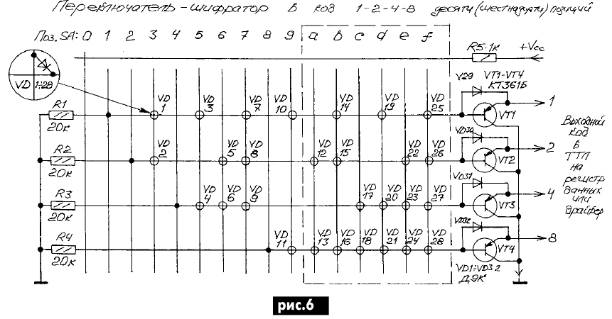
When mounting the clock button, one of the jumpers j1 is rearranged, a button is installed instead of the "frequency" resistor R *, and the resistor pads for restoring the circuit are connected by jumper jp2. In both circuits on an integrated timer (Fig. 4, a and b), only two frequency-setting elements R and C are used, of the same rating R \u10d 10 kOhm, C \u6d 7 μF. In the generator mode, a variable resistor, designated R *, is used to change the frequency, and due to the absence of a bit (second) resistor (between terminals 20 and XNUMX), the output pulses of the positive polarity generator have a short duration of the order of XNUMX μs, determined by the internal delay of the timer. The generator can be connected to a counter (to one of the clock inputs for counting up or down when viewing indicator symbols up to 9) or with a reset circuit in Fig. 1,b, if only symbols up to 6 are needed, or with three digits of a binary counter, you can view characters up to 7. Using the domino indicator and a pulse generator, it is easy to build a random pulse generator (an electronic analog of a rolling die). Together with the attached boards - 40x40 nodes, it can really fit inside the cube (children's set). In this case, the generator frequency should be increased to 100 Hz (for which the capacitance of the capacitor C should be reduced by 10 times), and the resistor R* should be bridged or removed. When the timer-generator stops, the indicator will display a random signal (when iterating over, all LEDs will light up). With a tact button, you can manually step through the characters or count the number of times the limit switch of a device has been triggered. If the counter on the driver board seems superfluous, then you can not install it or solder a 16-pin socket there, so that you can then insert an IE6 or IE7 counter. These counters are interesting in that they can not interfere with the transfer of data from inputs to outputs and even store data (they include a buffer register with potential control on the P input) and "grab" data from the stream. Figure 4d shows the inclusion of a reversible counter type IE6 or IE7 as a register. When the external load input P is grounded, the meter freely transfers data from the input to the output (to the indicator driver). As a simple and convenient source of data, I propose an implementation of another universal node - a coded switch (Fig. 6 and 7) in the code 1-2-4-8. Figure 6 shows the scheme of the encoder switch, which allows the implementation of encryption, both a binary 4-bit (for 16 positions) and a binary-decimal (for 10 positions) code. The printed circuit boards and the placement of the details of the last of them are shown in Fig. 7 on one biscuit of the 11P1N biscuit switch.
When implementing a binary-decimal switch in a 9x4 matrix, only 11 VD1 ... VD11 diodes were required, which are mounted on the switch head (in Fig. 6, the part for implementing the code for 16 positions is circled with a dotted line, but such an implementation will require a special switch). Since the circuit operates on TTL, it took 4 clamp transistors VT1 ... VT4 of the pnp type. The scheme of the clamps is made on a 40x40 printed circuit board, which is also a false panel (hides the switch nut under the panel). The encoder switch, generator and tact button in the form of the proposed finished units on unified boards are attached to the device panels with M2,5 screws through spacer bushings 5 mm high. The wiring diagrams (Fig. 5 and 7) show mounting options with the installation of the boards of the listed nodes with the side of the printed tracks to the panel. It is advisable to use the LEDs of the "domino" indicator with a red glow color (they are connected mainly by 2 pieces in series and when powered by +5 V they have a small voltage margin, and the green and yellow LEDs may not light up at all). You can apply a separate current-limiting resistor for each LED (as for HL1 in Fig. 2) or increase the supply voltage for the LEDs. With ultra-bright LEDs, the indicator (Fig. 3, a) could be seen from a distance of 100 m (at night, the characters could even be clearly distinguished with the naked eye). And all 9 LEDs turned on together (number 9) illuminate the room quite brightly. However, the red color is suitable, except for a photo lab, and the "white" ones are still a little expensive ... Author: Yu.P. Sarazha
Machine for thinning flowers in gardens
02.05.2024 Advanced Infrared Microscope
02.05.2024 Air trap for insects
01.05.2024
▪ The smell of disease passes from the sick to the healthy ▪ Radioactivity in the Egyptian pyramids ▪ Mattress for fast falling asleep
▪ site section Clocks, timers, relays, load switches. Article selection ▪ Narcissus article. Popular expression ▪ article Why did King Mithridates want to, but could not, commit suicide? Detailed answer ▪ article Digital tape recorder. Encyclopedia of radio electronics and electrical engineering
Home page | Library | Articles | Website map | Site Reviews www.diagram.com.ua |


 Arabic
 Bengali
 Chinese
 English
 French
 German
 Hebrew
 Hindi
Hindi Italian
 Japanese
 Korean
 Malay
Malay Polish
 Portuguese
 Spanish
 Turkish
 Ukrainian
 Vietnamese


 Leave your comment on this article: