
|
|
ENCYCLOPEDIA OF RADIO ELECTRONICS AND ELECTRICAL ENGINEERING Bench for testing electronic ignition blocks for chainsaws. Encyclopedia of radio electronics and electrical engineering
Encyclopedia of radio electronics and electrical engineering / Home, household, hobby The proposed device allows you to identify all faults on the desktop and test the electronic ignition unit in all modes of operation over the entire range of operating temperatures with the possibility of continuous and long-term monitoring of the device parameters with measuring instruments. Currently, the population has various mechanisms with carburetor engines, on which electronic ignition units are installed. And although in theory these devices should be highly reliable, since they do not contain mechanical contacts, in practice they often fail. Repair of such blocks is difficult for several reasons:
I want to share my own experience in repairing and testing electronic ignition units such as EM1, MB1 (several options), MB2, MB22. Such blocks are most often used on chainsaws and low-power outboard motors. Despite some differences in design, they all work on the same principle - this is a thyristor ignition circuit with a storage capacitor. Consider the principle of operation of these devices.
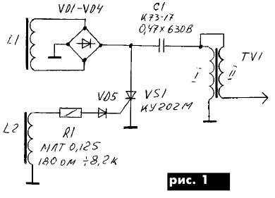
Figure 1 shows the power coil L1, in which, when the poles of the engine flywheel magnets move, an alternating voltage is induced past its core. It is rectified by a diode bridge VD1-VD4. Through the winding I of the high-voltage transformer TV1, the storage capacitor C1 is charged. Coil L2 (control coil) is also in the changing magnetic field of the engine flywheel. When the piston approaches the top dead center, a positive polarity voltage appears on its ungrounded output, which, through the resistor R1 and the diode VD5, is fed to the control electrode of the thyristor VS1. The thyristor opens, the capacitor C1 is quickly discharged through the winding I of the transformer TV1, a high voltage pulse is excited in the winding II. A spark plug is connected to the output of this winding, where a "spark" is formed. After the discharge of the capacitor C1 to a certain value, the thyristor closes. A new charge cycle begins and all processes are repeated. The parameters of the circuit elements are given in Table. one.
Structurally, the blocks EM1 and MB1 look as shown in Fig.2. In them, the cores of the power and control coils are separated in space. The high-voltage transformer is fixed with the same screws as the control coil, but it does not have an external core, so it is weakly affected by external magnetic fields.
The whole device is in the magnetic field of permanent magnets fixed in the engine flywheel. However, the poles of the magnets are oriented and arranged in such a way that for one complete revolution of the crankshaft, four periods of alternating pulsed voltage are induced in the power coil, and one in the control coil. Figure 3 shows the voltage oscillograms obtained on the stand, which will be discussed below. These diagrams are close to real ones. In measurements, to eliminate distortions in the shape of the studied signals, a voltage divider of 1:10 was used and an open input of the oscilloscope was used. Since these voltages are decisive for the high-quality operation of the unit, we will analyze them in more detail.
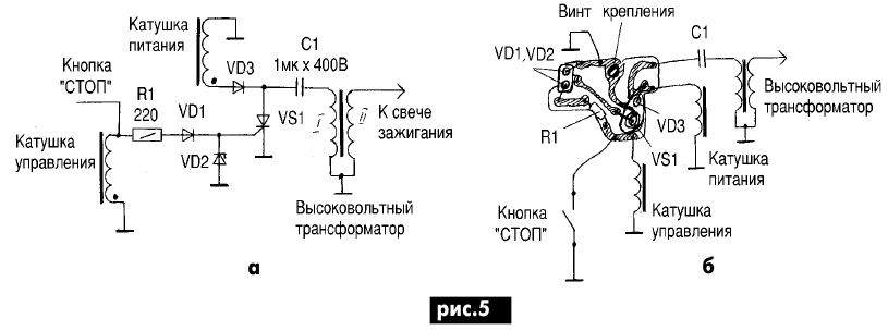
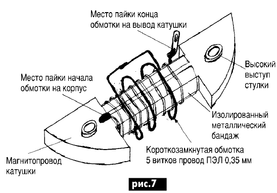
For the circuit in Fig. 1, the power coil is connected to the load through the diode bridge VD1-VD4, so the voltage shape on it is symmetrical. Some distortions of one half-cycle arise due to the asymmetry of the change in the magnetic field generated by the stand, but this is not of fundamental importance (Fig. 3a). With each period, the capacitor C1 is charged in steps to a voltage approximately equal to the voltage on the power coil (Fig. 3d). After four charge cycles, a positive impulse appears on the control coil (Fig. 3b). We will talk about the negative surge of this impulse later. The control pulse (Fig. 3, c) through the limiting resistor R1 and the protective diode VD5 opens the thyristor. The capacitor is discharged through winding I of the high-voltage transformer to a few volts, and then the process is repeated. It would seem that now that we know how the electronic ignition unit works, there is nothing easier to check it. However, in the vast majority of cases, you will not be able to do this. And most often it happens that if you charge the capacitor C1 from an external source of constant voltage and open the thyristor, you can get a spark, but the unit does not work on the engine. Have you ever "meet" a chainsaw that starts well "hot" ?. That's great rarity. Also, the engine runs intermittently. There comes an endless replacement of candles, cleaning the carburetor, and the result is zero. Before moving on to talking about a test bench that will help identify almost any damage, let's return to the concept of EM and MB blocks. Resistor R1 in Fig. 1 (option I) is selected during the tuning process within 180 ... 1200 Ohms. In this case, we are talking about the spread of the parameters of the thyristors, the magnetization of the permanent magnets of the rotor, the gap between them and the core of the control coil, as well as the parameters of the coil itself. The main purpose of this resistor is to limit the current of the control electrode of the thyristor VS1. In the subsequent modification of MB1 (option II), the diagram of which is shown in Fig. 4, the control coil has a short-circuited winding II, which reduces the likelihood of high-voltage high-frequency surges in winding I. This eliminated the need to select a limiting resistor R1. Please note that in both versions, the capacitor C1 is charged from the power coil through the diode bridge. Therefore, the polarity of connecting its outputs does not matter. In option III (Fig. 5), the thyristor control electrode is shunted by the VD2 zener diode, which limits the thyristor control voltage. Therefore, it depends little on the engine speed. From the winding of the control coil, a wire is led to the "Stop" button, which, when pressed, shorts the thyristor control circuit to the housing. However, try to never use this button, except in emergency situations, otherwise the electronic ignition unit may be disabled. In all of the above options, the diode VD1 protects the control electrode of the thyristor from the reverse control voltage. Common to these circuits is the fact that the same control electrode is practically "hanging in the air." Such a solution does not at all contribute to the stability of the blocks, and only due to the fact that a relatively small power is dissipated on the thyristor, it still somehow works in this mode. A distinctive feature of option III from options I and II is that capacitor C1 is charged from the power coil through a half-wave rectifier VD3. It would seem that the generator power is only used by half, but the spark in such blocks is more intense and more stable. However, the polarity reversal of the power coil leads changes the moment of charge of the capacitor C1 in time. This leads to a deterioration in the operation of the unit or to its complete stop. This coil has different parameters compared to coils in variants I and II. Therefore, their mutual replacement is not equivalent. Further improvement of electronic ignition devices led to the scheme of Fig. 6, called the EM1 block. Structurally, it is no different from the previous blocks, but in it the control electrode of the thyristor is shunted by resistor R2, which put its operation in standard mode. Diode VD2 does not affect the positive surge of the control voltage, but shunts the negative one. At the same time, the control coil is constantly loaded, which excludes its high-voltage breakdown, which cannot be said about the power coils in the EM and MB units in option III. Now let's talk about the malfunctions that occur during the operation of the blocks. They can be conditionally divided into two groups: 1) does not work at all; 2) works intermittently. As a rule, it is easier to detect damage in case of malfunctions of the 1st group. Of course, the block must be removed from the engine. A close external examination can reveal mechanical damage: damage to the coils by the rotor or the previous "specialist", poor soldering of the leads, as well as rough attempts to access the printed circuit board. You can try to ring the coil winding tester for an open circuit. In this case, it should be borne in mind that their resistance has a large spread, and we can only talk about detecting a break. Approximately these are the following values: power coils 0,8 ... 2,0 kOhm; control coils 50...100 Ohm; high-voltage transformer: winding I 0,8 Ohm, winding II 2 ... 3 kOhm. The easiest way to repair the control coil. Its design and the winding direction of the windings are shown in Fig. 7.
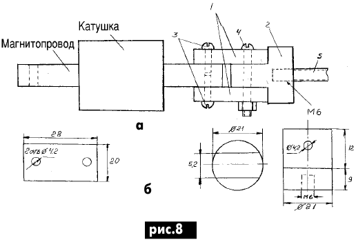
Winding data are given in table.1. Do not try to unwind the spool. A break usually occurs at the beginning of the winding. It is better to cut it with a knife and a hammer. The high protrusions of 4 fastening sleeves make it possible to unambiguously determine the direction of winding of the control coil and the place of fastening of its output. Changing the winding direction will greatly change the decay advance angle. In which direction the shunt winding is wound does not matter. The control coil is wound turn to turn with interlayer insulation. However, to fix the coil core in the winding machine, it is necessary to make a device, the design of which is shown in Fig. 8. It consists of a curly boss 2, which is threaded to the axis of the winding machine 5 and two getinax plates 1, through which, using screws 3 and 4, the magnetic circuit is attached to the boss (if you have never rewound winding products, ask for help from more experienced friend). The same device is also used to rewind the power coil and high-voltage transformer.
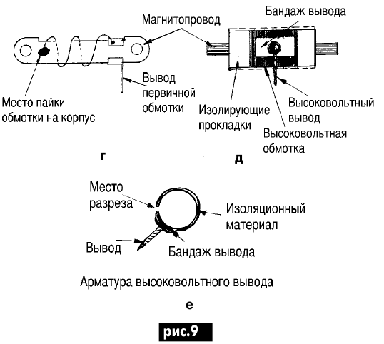
The power coil is the simplest in design and is wound in bulk on a plastic frame. There are two types of such coils: with a bandage of glass tape (with subsequent impregnation with varnish) and pressed with polyethylene. When disassembling these coils, you can, if desired, partially preserve its winding, but this is impractical. It is also better to cut them in the above way without destroying the frame. Given the non-criticality of this winding, it can be wound with a suitable wire without counting the turns, guided by the filling of the frame. But at the same time, the winding must be dense, and the conclusions are fixed rigidly in order to eliminate friction during engine vibration. The most difficult to repair is a high-voltage transformer, or as it is often called a "reel". To repair it, experience with thin wires and decent patience are simply needed. The design of the transformer is shown in fig. 9.
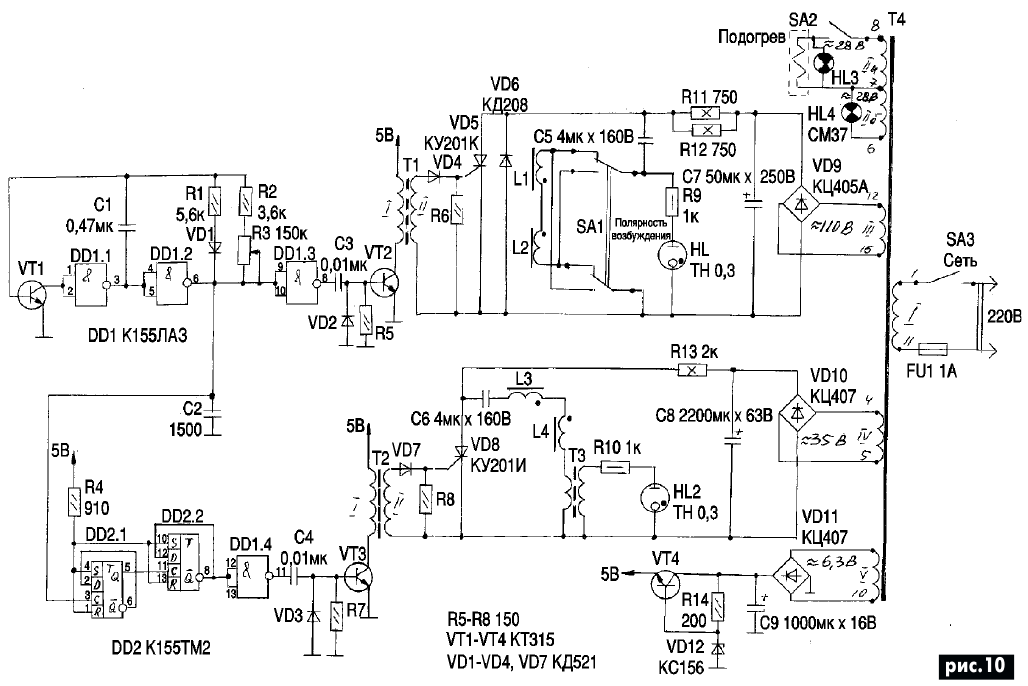
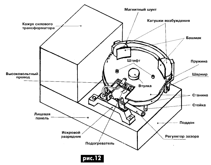
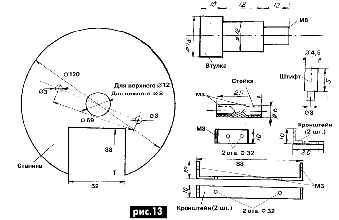
To disassemble it, the polyethylene bandage must be cut from three sides along the lines shown in Fig. 9, a, b, c. The resulting lid opens as shown in Fig. 9c. The transformer itself is taken out by the magnetic circuit. But first you need to remove the primary winding terminal, and then the high voltage screw terminal. Since the direction of its windings does not really matter, it is also easier to cut them. Not trying to save the primary winding. Strictly speaking, if the transformer windings are connected in concert, then the voltage on the high-voltage wire will be higher, although not so much that it can be noticed. If the winding of the primary winding does not present any difficulties, then the situation with the secondary is much more complicated. Take another look at Table 1, and if you do not have suitable insulation or wire of the specified diameter (it can be somewhat thinner), then further work is meaningless for the following reasons: with a wire diameter or insulation thickness greater than the specified winding does not fit into the bandage that protects from mechanical and electrical damage. If you use oil-impregnated transformer paper insulation, it will not work for a long time, and the fluoroplastic film will not allow you to lay the wire turn to turn, which will ultimately lead to turn-to-turn breakdowns. But if everything is at hand, then after disassembling the coil, it is advisable to keep the glued coil fittings together with the high-voltage output fixed to it. As shown in Fig. 9, f. As the winding of the secondary winding, leave more and more fields at the edges (Fig. 9, e) in order to avoid electrical breakdown between the upper and lower layers. The number of turns does not require a strict calculation, but the outer diameter of the winding must be observed, otherwise the winding will either not fit in the bandage, or will hang out during engine operation and will inevitably fail. After installing the fittings of the high-voltage wire, it must be tied up with thin, strong threads. The coil can be tested on a stand without a bandage. If the unit is installed on the motor, be sure to complete the assembly of the transformer in the reverse order, inserting the low-voltage terminal in its place. Seams gently melt with a hot soldering iron, avoiding solder. The schematic diagram of the stand is shown in Fig.10. It consists of a pulse generator assembled on VT1, DD1.1, DD1.2 with an adjustable pulse repetition rate from 0 to several hundred hertz, set by a variable resistor R3. Changing the frequency is equivalent to changing the engine speed. Pulses through the inverter DD1.3 are fed to the base of the transistor VT2, the load of which is the pulse transformer T1. Opening, the thyristor VD5 discharges the capacitor C5 through the excitation windings of the power coil L1 and L2, the excitation polarity switch changes the direction of the magnetic flux. Indicator lamp HL1 is used to control the presence of excitation pulses and their frequency. On triggers DD2, a frequency divider by 4 is assembled - in the excitation coils L3 and L4 of the control winding, current pulses are formed after every fourth pulse in coils L1, L2. The only difference between this excitation channel is the presence of a power supply circuit for the HL2 indicator lamp, which is connected to the power supply circuit of the coils through a step-up transformer T3. In the power supply, you need to install resistors R11, R12 and R13 of the required ratings. If you use a transformer with other output voltages, then the values \uXNUMXb\uXNUMXbof these resistors must be changed accordingly. The SA2 toggle switch turns on the heater, which, on the one hand, allows you to increase the operating temperature of the block, and on the other hand, it heats the compound until it softens without deforming the polyethylene crimping of the coils of the block. For this purpose, a part of a spiral from an electric iron with porcelain insulators was used. The power transformer must provide power in loads of at least 60 watts. In the described design, a ready-made one is used, therefore, only the voltages on the secondary windings are shown in the diagram. Pulse transformers T1 and T2 are wound on ferrite rings K18Ch8Ch5 brand 2000HM. All windings are the same and contain 40 turns of insulated wire D0,2 mm. Coils L1 and L2 each contain 180 turns of wire D0,3 mm, and L3, L4 - 55 turns of wire D0,6 mm each. All of them are wound on cores made from the boots of the excitation winding of the faulty generator of the motorcycle "Java - 350/360.00" cut in two along the height (Fig. 11., b). However, it would be preferable to make it from transformer steel, using for this purpose structural elements of some electric motor suitable in diameter. The shoes are fixed on steel curved magnetic shunts (Fig. 11, a), which, in turn, are movably mounted on the frame with the help of hinges (Fig. 11, c) made of non-magnetic material (Fig. 12). The bed consists of two disks (Fig. 13), pulled together by a sleeve. A heating coil is laid between the disks on an asbestos gasket. For thermal insulation, this structure is fixed on the pallet of the stand using three racks. The bushing and pins are used to fix the unit under test on the stand. The remaining structural elements are extremely simple and do not require explanation. On fig. 12, for simplicity, the control coil excitation assembly is not shown, which structurally repeats the power coil assembly. Both of them recline on hinges, held in working condition by springs, which ensures their tight fit to the cores of the ignition unit. As a spark gap, a ready-made adjustable lightning arrester, which was widely used in communication equipment, was used. It is better to sharpen the ends of the discharge screws. In this case, the length of the spark, although it will not correspond to the length of the spark in the spark plug, will allow you to more accurately set the discharge mode. If the discharge surfaces are rounded off (like a spark plug), then the discharge gap will decrease significantly and it will be more difficult to regulate it. Stand details do not require high precision and therefore can be made in a handicraft way at home. Approximate overall dimensions of the stand: width 250 mm, height 140 mm, length 135 mm. All controls and indicator lamps are installed on the front panel of the pallet (not shown in the figure). The order of work with the stand. Unscrew the rotary excitation units and install the ignition unit on the frame. In this case, it will be fixed with a bushing and pins in the position when the high-voltage coil is directed towards the spark gap. Release the nodes of excitation. They should be pressed against the ignition block by springs. Insert the high-voltage wire of the arrester into a high-voltage transformer (the second terminal of the arrester is, of course, grounded). Set the gap of the arrester to 1,5-2 mm, the frequency control to the minimum and turn on the power. Turn the knob until you get the frequency you are interested in. The spark in the gap must be stable, without interruption over the entire frequency range. In some cases, at the highest frequency, the thyristor may not have time to close, then reduce the frequency and click the power switch. Decrease and increase the gap of the arrester. With a large gap, the spark should not disappear (up to 5 ... 6 mm). Tilt the power coil exciter assembly. The spark will become weaker and, finally, disappear - the supply voltage of the unit will decrease. By the maximum possible deflection angle, at which the spark is still preserved, one can judge the quality of the block. Set the center frequency, and if you want to test the block for electrical strength, slowly deflect the control coil excitation assembly. The spark becomes intermittent, but powerful. But in this mode, the block should not work for a long time (and cannot). If, after such a test, he refused, then he probably could not work normally on the engine. Power on the heater and set the middle frequency. During normal operation of the unit and a gap of 3 mm, the nature of sparking in a heated state remains practically unchanged. Now connect an oscilloscope to the MB. It is more convenient to replace packageless diodes with KD102B or KD103B (also with a blue dot, but the latter has a black body color). The reverse voltage of KD103B is only 50 V, but it is better to install a 2D102B diode with an orange dot. Usually, replacing one element does not provide significant improvements in the operation of the block. It is better to replace the bridge diodes all at once. And if the leak still remains (the oscilloscope shows a dotted graph (see Fig. 3.d in RE7 / 2001), before taking it for a thyristor, try replacing the capacitor with a known good one. It should be borne in mind that the spark will depend on its capacitance as follows: when it decreases, the capacitor has time to charge to a high voltage, and therefore a pulse of less power, but more voltage is formed in the secondary winding of the transformer.At first glance, the spark seems to be getting better, but in the engine, incomplete combustion of the fuel mixture occurs.If after that, nevertheless, the "saw" remained, and the spark is weak and intermittent, then you will have to replace the thyristor - take out the thyristor of the KU202M, N type on the wires and fix it somewhere in a suitable place. By the way, you can do the same with a high-voltage transformer if you take it from a moped or motorcycle. You can take a crystal from a good serviceable thyristor and install it instead of the failed one as follows: first you need to disassemble the KU202M or N thyristor (before disassembling, be sure to ring it well, including in a heated state). To do this, carefully cut the thyristor leads with side cutters or a needle file to free the flagella of the crystal leads. In this case, it is important not to rivet the tubular leads of the anode and control electrode. Cut off the cathode threaded lead with a hacksaw near the case itself. Clamping the thyristor in a vise, preventing its deformation, as close as possible to the body in a circle, cut off the weld of the thyristor cover, then turning it with pliers. The lid will pop off. Carefully remove its top, access to the crystal will open. If it turns out to be square, your work has gone down the drain, it is impossible to separate the crystal from the case (although the thyristor can still be used). But if it is round, heat the body of the thyristor with a powerful, well-heated soldering iron, capturing all the leads with thick tweezers or long-nose pliers as close to the crystal as possible. To speed up the process of dismantling the crystal, put more solder on the soldering iron to increase the heat transfer area. If the crystal is coated with a sealing compound, carefully remove it first. When installing the dismantled chip on the heat sink of the control circuit board, first warm up the installation site well, and then attach a new chip to it and take care of the rapid cooling of the structure, preventing tin-lead solder from getting into the soldering site. This operation must be done as quickly as possible. Use low-temperature solders for soldering, and therefore the expression "warm up well" should be understand in the sense of melting the remnants of this solder on the heat sink. The thyristor leads will not get mixed up: the anode one is longer and thicker. And in conclusion, a few words about the characteristic malfunctions of the EM and MB blocks. Most often, high-voltage transformers fail. Then the ignition either does not work at all, or gives a very weak spark with all normal waveforms. As a rule, when heated in diodes and a thyristor, leaks appear in almost all blocks, but to a greater or lesser extent, therefore, after replacing the diodes, do not rush to change the thyristor. If all other elements are normal, then the unit can work satisfactorily with such a thyristor.
It happens that after warming up, the unit abruptly stops working, and after cooling it is restored, and also abruptly. This phenomenon is observed when the soldering of the output of the thyristor control electrode is disturbed. During normal operation, the control voltage pulse is 3 V (Fig. 14, a), and during a break - up to 50 V (Fig. 14, b). Figure 15 shows the voltage waveform on the power coil of a half-wave rectifier. A positive pulse characterizes the process of charging the capacitor, and a negative pulse characterizes the closed state of the rectifier diode. Author: V. M. Paley
Machine for thinning flowers in gardens
02.05.2024 Advanced Infrared Microscope
02.05.2024 Air trap for insects
01.05.2024
▪ A healthy liver is grown from a diseased donor ▪ ASUS Hyper M.2 X16 Card V2 Expansion Card ▪ Photosynthetic engine for artificial cells
▪ section of the site Data transfer. Article selection ▪ article To die is to fall asleep. Popular expression ▪ article Which metropolis has no outdoor advertising at all? Detailed answer ▪ article Crotalaria sitnikovaya. Legends, cultivation, methods of application ▪ article Extinguishing match. Focus secret
Comments on the article: Anatoly After many hours of wandering through the search engines, this article is a balm for the soul! Thank you, dear Paley V.M. [up]
Home page | Library | Articles | Website map | Site Reviews www.diagram.com.ua |


 Arabic
 Bengali
 Chinese
 English
 French
 German
 Hebrew
 Hindi
Hindi Italian
 Japanese
 Korean
 Malay
Malay Polish
 Portuguese
 Spanish
 Turkish
 Ukrainian
 Vietnamese






 Leave your comment on this article: