|
|


 Arabic
 Bengali
 Chinese
 English
 French
 German
 Hebrew
 Hindi
Hindi Italian
 Japanese
 Korean
 Malay
Malay Polish
 Portuguese
 Spanish
 Turkish
 Ukrainian
 Vietnamese
|
ENCYCLOPEDIA OF RADIO ELECTRONICS AND ELECTRICAL ENGINEERING Light regulator. Encyclopedia of radio electronics and electrical engineering
Encyclopedia of radio electronics and electrical engineering / Lighting I suggest a simple dimmer. It differs from similar ones in high technical characteristics, good repeatability and simplicity.
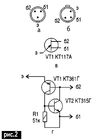
The device is assembled on a unijunction transistor VT1 (Fig. 1) and contains a powerful trinistor VS1, which is loaded on chandelier lamps (conventionally designated HL1). The power supply is made on VD1, VD2, R5. Diode VD2 is rectifier, resistor R5 is limiting, VD1 is a stabilizing zener diode. The moment of switching on VT1 relative to the beginning of the half-cycle depends on the constant voltage across the resistor R4 and on the smoothly increasing voltage across the capacitor C1. As soon as these voltages become approximately equal, the transistor VT1 opens (along the emitter). As a result, the next half-wave of the mains voltage is almost completely (at a high brightness of the glow) or partially (at a low brightness of the glow) through an open trinistor VS1 is applied to the lamp HL1. Thus, the greater the resistance in the charge circuit of the capacitor C1 (R1), the later the trinistor VS1 turns on and the lower the brightness of the HL1 glow. Details. Diode VD2 - any small-sized silicon. Zener diode VD1 - any low-power with a stabilization voltage of 10-15 V, for example KS210Zh, KS212Zh, KS213Zh, 2S210Zh, 2S211Ts, 2S212Ts, KS215Zh, D814V1, D814G1, D814D1, 2S516A. Trinistor VS1 - any type KU202 (with the letter index K or L) with a rated lamp power HL1 up to 400 W or type KU202 (with the index K, L, M, N) with a lamp power up to 200 W. Trinistor VS1 should be installed on a small heatsink with lamp power HL1> 1500 W. Bridge VD3 - type KTs402 or KTs405 (with index Zh or I) with lamp power up to 120 watts. If the lamp power does not exceed 60 W, the bridge can be assembled from four diodes KD105 (with index B, C, D) or D226 (B or C); if the lamp power does not exceed 100 W, then from KD209 diodes (with index A, B, C) or KD205 assemblies (A, C, F or M); if the lamp power does not exceed 350 W, then from diodes KD202 (K, M, R); if the lamp power does not exceed 2000 W, then from any 10-ampere diodes with a reverse voltage of 400 V or more, for example, D233, D246, D247, KD203 (from A to D), KD206 (A, B or C), KD210 (from A to D). Capacitor C1 - any ceramic or metal paper. Resistors R2-R4, R6 - type MLT-0,125, OMLT-0,125, VS-0,125; R5 - type MLT-2; R1 - any variable. Instead of R1, you can use a photodiode, photoresistor or thermistor, so you can build a thermal stabilizer or light stabilizer. Transistor VT1 can be used type KT117 (Fig. 2, a shows the pinout of obsolete types of transistors, and Fig. 2, b shows the pinout of modern ones). If you don’t have such a unijunction transistor (Fig. 2, c), it will be completely replaced by the analog shown in Fig. 2, d.
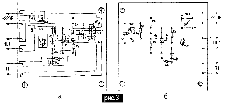
You can use conventional (bipolar transistors of the following types: pnp (VT1) structures of the KT208, KT209, KT213, KT361, KT501, KT502, KT3107 types; npn (VT2) structures of the KT315, KT340, KT342, KT503, KT3102 types. The design of the regulator is arbitrary, taking into account element base of radio amateurs.It can be simplified by excluding VD3 from the circuit.In this case, the lamp will only heat up to 50%.If 100% is necessary, then you need to replace VS1 with a KU208G triac and install it on a radiator with a power of HL1 more than 1500 watts. I suggest that the regulator be made on a printed circuit board made of foil material (I do not recommend using getinaks, since the foil often peels off) 60x60 mm in size. Figure 3a shows the printed circuit board from the side of the printed conductors, and Figure 3b shows the side of the radio components. It can be etched in a solution of ferric chloride or cut through with a cutter knife.
The device is housed in the lighting switch housing. Resistor R1 is located on the front panel. A decorative handle is put on the resistor. It can be made from the cap of a tube of toothpaste. Make a hole in the cover corresponding to the diameter of the rotor of the resistor R1. Lubricate the cover with superglue and put it on the resistor rotor. Author: K. Gerasimenko
Air trap for insects
01.05.2024 The threat of space debris to the Earth's magnetic field
01.05.2024 Solidification of bulk substances
30.04.2024
▪ The Gulf Stream slowed down due to global warming ▪ Growing seafood in laboratories ▪ Dehydrated mosquitoes bite more often
▪ site section Measuring equipment. Article selection ▪ article Earth and water. Popular expression ▪ How did animals get their names? Detailed answer ▪ Article Halong Bay. Nature miracle
Home page | Library | Articles | Website map | Site Reviews
www.diagram.com.ua |


 Leave your comment on this article: