|
|


 Arabic
 Bengali
 Chinese
 English
 French
 German
 Hebrew
 Hindi
Hindi Italian
 Japanese
 Korean
 Malay
Malay Polish
 Portuguese
 Spanish
 Turkish
 Ukrainian
 Vietnamese
|
ENCYCLOPEDIA OF RADIO ELECTRONICS AND ELECTRICAL ENGINEERING Electronic fuse with digital indicator. Encyclopedia of radio electronics and electrical engineering
Encyclopedia of radio electronics and electrical engineering / Protection of equipment from emergency operation of the network The proposed device performs the functions of a self-restoring fuse and is designed to protect against current overloads of various radio-electronic equipment powered by direct voltage.
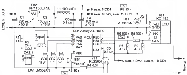
The basis of the device (Fig. 1) is the DD1 microcontroller, which operates according to the program, the codes of which are given in the table. It measures the flowing current, compares it with a pre-set value of the protection threshold, displays information on the LCD indicator HG1 and controls a powerful switching field-effect transistor VT1.
Main Specifications Input voltage, V ........6...30
The function of the current sensor is performed by the resistor R4. The voltage on it is proportional to the current flowing through the load, it goes to the DC amplifier on the op-amp DA2.1, and the already amplified voltage through the buffer amplifier-follower of the voltage on the op-amp DA2.2 - to the PAO line of the DD1 microcontroller, which is configured as an input built into it ADC. The reference voltage of the ADC (2,56 V) is output to the RVZ output (pin 17) of the microcontroller and is additionally filtered by capacitor C5. A parametric voltage regulator on resistor R5 and LED HL1 provides power to a ten-digit LCD indicator HG1 with a voltage of about 1,5 V, resistive dividers R6R7 and R8R9 are designed to match the output signals of the microcontroller with the inputs of the HG1 indicator. The ADC of the microcontroller operates in continuous conversion mode with a clock frequency of about 250 kHz. When processing an interrupt upon completion of the conversion, the codes in the ADC registers are compared with the codes in the buffer registers (hereinafter referred to as the setting ones), which correspond to the protection threshold. If the flowing current is less than the set threshold, the transistor VT1 is open and the supply voltage is supplied to the load. When the current reaches or exceeds the threshold value, the transistor VT1 closes for about 60 μs, turning off the load. After that, every 0,5 s, the transistor VT1, at the command of the microcontroller DD1, will open, and if the current overload is eliminated, the transistor will remain open. The values of the flowing current and the threshold are displayed on the indicator HG1. The right side of it displays the value of the threshold current. In the extreme right (first) category - hundredths of an ampere, in the second - tenths, the third is extinguished and in the fourth - units of amperes. Similarly, on the left side of the indicator (bits 7-10) the value of the current flowing through the load is displayed. If this current exceeds 9,99 A, "-" signs are displayed on the 7th, 8th and 10th digits. By pressing the SB1 button, the protection threshold is set to 5 A. The software prohibits the jumping of codes in the setting registers (from 0 to 999, and vice versa). By pressing the button SB2 "-" or SB3 "+" change this value in variable increments. When one of these buttons is constantly held down, the first ten threshold values change with a resolution of 0,01 A, then it increases to 0,1 A. After releasing the button, the step returns to its original value - 0,01 A. The device allows you to determine the maximum starting load current. To do this, press the button SB4 "Mode". Before processing the interrupt from the ADC, the codes from the setting registers are copied to the general-purpose registers of the microcontroller, and when processing the interrupt, they increase by 10, which corresponds to an increase in the protection trip current by 0,1 A. If the "Mode" button is held down, the value of the protection trip current increases by 0,1 A every 0,5 s and is displayed on the right side of the indicator. After connecting the load (if necessary), reduce the protection current value with the SB2 "-" button. This feature is useful when the capacitors in the load power filters are large. If the SB4 "Mode" button is not pressed, the value of the setting registers is restored and the value of the protection operation current returns to its original value.
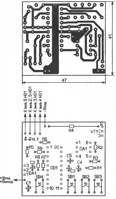
Most of the parts are placed on a printed circuit board made of one-sided foil fiberglass, the drawing of which is shown in Fig. 2. Resistor R4 - wire, dismantled from a faulty digital multimeter of the M83x series, fixed resistors - MLT, S2-23, oxide capacitors - imported, the rest - KM, K10-17, LED - any red glow with a direct voltage drop of 1,5 ...1,7 V at a current of 0,3 mA, the inductor is an imported EU-24, it is soldered from the side of the printed conductors to the contact pads of pins 5 and 15 of the microcontroller. The negative output of the device is connected (soldered) to the flange of the transistor VT1. To establish, a series-connected resistor with a resistance of 6 ... 10 Ohms, a power of 25 W and a reference ammeter are connected to the output of the device. By changing the input voltage, the output current is set to 1 ... 1.5A, and by selecting the resistor R1, the readings on the left side of the HG1 indicator and the ammeter are equalized. The microcontroller program can be downloaded hence. Author: M. Ozolin, p. Krasny Yar, Tomsk region; Publication: radioradar.net
Machine for thinning flowers in gardens
02.05.2024 Advanced Infrared Microscope
02.05.2024 Air trap for insects
01.05.2024
▪ Long-term use of ibuprofen is dangerous for men ▪ A new source of green energy ▪ Autonomous powered marine robot drone ▪ New series of MINI DORADO LEDs
▪ section of the Electrician website. PUE. Article selection ▪ article Ushinsky Konstantin Dmitrievich. Famous aphorisms ▪ article Which bird migrates the greatest distances? Detailed answer ▪ article Seamstress (tailor). Job description ▪ article Alto sound simulator. Encyclopedia of radio electronics and electrical engineering
Home page | Library | Articles | Website map | Site Reviews
www.diagram.com.ua |


 Leave your comment on this article: