|
|


 Arabic
 Bengali
 Chinese
 English
 French
 German
 Hebrew
 Hindi
Hindi Italian
 Japanese
 Korean
 Malay
Malay Polish
 Portuguese
 Spanish
 Turkish
 Ukrainian
 Vietnamese
|
ENCYCLOPEDIA OF RADIO ELECTRONICS AND ELECTRICAL ENGINEERING Device for protecting equipment from abnormal voltages of the network. Encyclopedia of radio electronics and electrical engineering
Encyclopedia of radio electronics and electrical engineering / Protection of equipment from emergency operation of the network The protective device developed by the author in terms of the functions performed is similar to that described in the article by I. Kotov "Device for protecting equipment from emergency mains voltage" ("Radio", 2008, No. 8, pp. 26, 27). It does not contain a step-down transformer, and a triac is used to switch the load, which increases the speed of protection.
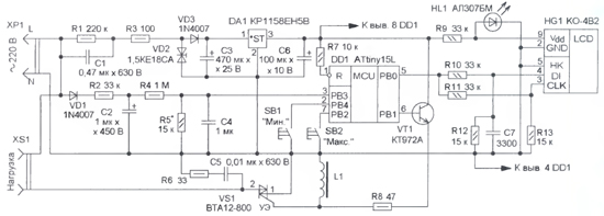
The proposed device disconnects the load from the 220 V mains both when the mains voltage exceeds or falls below predetermined values. The basis of the device (Fig. 1) is the DD1 microcontroller, which operates according to the program, the codes of which are presented in the table. From the mains voltage, the limiting diode VD2 forms an alternating (close to rectangular) voltage with an amplitude of about 18 V. Capacitor C1 is current-setting, resistor R3 limits the starting current when connected, and R1 ensures that capacitor C1 is discharged when the device is turned off. Diode VD3 rectifies this alternating voltage, and capacitor C3 smoothes out the ripple. Stabilizer DA1 provides power to the microcontroller with a voltage of 5 V. Varistor RU1 protects the triac VS1 from voltage surges when switching an inductive load. Control of the value of the mains voltage is carried out by the built-in ADC of the microcontroller DD1. To do this, the mains voltage is pre-rectified by the diode VD1 and through the low-pass filter R2C2 and the resistive voltage divider R4R5 is fed to the input of the ADC (pin 3) of the microcontroller DD1. Capacitor C4 additionally suppresses impulse noise. After conversion to the ADC, the ten-bit result is shifted one bit to the right and the least significant bit is ignored. As a result, the ADC data is nine bits wide.
The supply and disconnection of the mains voltage from the load are carried out by the triac VS1. To open it with a timer-counter 1 of the DD1 microcontroller, pulses with a frequency of 1 kHz and a duty cycle of 6 (duty ratio 10) are generated on the PB0,1 line (pin 10). After current amplification by the transistor VT1, these pulses through the resistor R8 are fed to the control electrode of the triac VS1. Due to the high frequency of the control pulses, it opens at the beginning of each half-cycle of the mains voltage, which reduces the level of switching noise. The R6C5 circuit is intended for the same purpose. Load disconnection is provided by stopping the timer-counter 1 and setting the voltage to a low level on the PB1 line of the DD1 microcontroller. On the ten-digit LCD indicator HG1, the three least significant (rightmost) digits display the mains voltage, the fourth and fifth are separating ones, they are extinguished. In the sixth, seventh and eighth digits with a frequency of 1 s, the maximum and minimum cut-off voltages are alternately displayed. The ninth digit is separating (off), and the tenth digit displays the time (in seconds) remaining until the load is turned on when the mains voltage is within the specified limits. Buttons SB1 and SB2 change the values of the threshold voltages for switching off the load, the minimum and maximum, respectively. When these buttons are pressed simultaneously, the value of the variable mains voltage is displayed, and after they are released, it returns to the alternation of the minimum and maximum cut-off voltages. When you press the button SB1 "Min." the minimum shutdown threshold changes every second from 160 to 210 V in steps of 5 V. If it is held for a long time, after reaching the maximum value (210 V), the minimum value (160 V) is set and then increased again. Similarly, when you press the button SB2 "Max." the value of the maximum threshold periodically changes from 230 to 255 V in steps of 5 V. If the mains voltage goes beyond the set thresholds, the load is disconnected from the mains for 10 ms, and the number 7 is displayed in the older one. After the voltage returns to normal, this bit displays a countdown of a seven-second time interval, after which the load will be connected to the mains, and the rank is extinguished. If during the countdown the mains voltage goes beyond the set limits, the load will remain in the off state, and the countdown of the interval will start again. Since the number of lines of the port of the microcontroller DD1 is limited, the data and synchronization signals to the LCD indicator HG1 are transmitted via a single-wire interface with time-pulse coding (the duration of the transmission of a single bit is about ten times longer than zero). The indicator supply voltage (about 1,5 V) is taken from the HL1 LED, which works as a voltage limiter.
All parts, except for buttons, are installed on a printed circuit board made of one-sided foil fiberglass 1,5 ... 2 mm thick, the drawing of which is shown in fig. 2. The buttons are mounted on the front panel of the case, made of insulating material. Mounting holes are made for them, and a window for the indicator. The indicator itself is fixed on the board with the help of racks about 40 mm high. Resistors MLT, C2-23, oxide capacitors are imported, C1, C5 - K73-17, C4, C7 - K10-17. Throttle - DM-0,1 with an inductance of 500 μH, buttons - KM-1 or similar with self-return. To establish the device, together with an exemplary voltmeter, is connected to the network and a selection of resistor R5 achieves on the LCD indicator of the device the mains voltage readings corresponding to the readings of the reference voltmeter. When setting up, it should be borne in mind that all elements of the device are under mains voltage. The protection device microcontroller program can be downloaded hence. Author: M. Ozolin, p. Krasny Yar, Tomsk region; Publication: radioradar.net
Machine for thinning flowers in gardens
02.05.2024 Advanced Infrared Microscope
02.05.2024 Air trap for insects
01.05.2024
▪ Biochemistry for automotive fuel ▪ The influence of foods on a person's mood ▪ Old phone: heat up after use
▪ section of the site Firmware. Article selection ▪ Article Standard instructions for labor protection. Types of jobs. Directory ▪ article How dangerous are asteroids? Detailed answer ▪ article Doctor-allergist-immunologist. Job description ▪ article Vertically floating match. Focus Secret
Home page | Library | Articles | Website map | Site Reviews
www.diagram.com.ua |


 Leave your comment on this article: